Yaskawa DI-08 User Manual
Digital input option card di-08
Yaskawa Electric America, Inc. – www.drives.com
IG.AFD.58, Page 1 of 3
Date: 07/01/04, Rev: 04-07
Digital Input Option Card
DI-08
Part Number: DI-08.
Applicability: F7, G7, GPD515/G5, G5HHP.
Note: If used in a GPD 503/G3, refer to Instruction Sheet
02Y00025-0294.
Introduction: The DI-08 digital input option card is mounted
on the drive’s control board and allows the user to interface an
8-bit digital speed reference to the drive. This reference can be
binary, binary coded decimal (BCD) in hertz, or BCD in
percent. Sign (polarity) and Set (load) inputs are also included.
Receiving: All equipment is tested against defect at the
factory. Report any damages or shortages evident when the
equipment is received to the commercial carrier who
transported the equipment.
Warning: Hazardous voltage can cause severe injury or
death. Lock all power sources feeding the drive in the “OFF”
position.
Caution: This option card uses CMOS IC chips. Use proper
electrostatic discharge (ESD) protective procedures when
handling the card to prevent I.C. damage or erratic drive
operation.
Important:
1. If this option card is being installed in a drive with an
encoder (PG) feedback option card, that card will
need to be to temporarily removed to allow access to
connector 2CN on the drive’s control board and TC1-
TC11 on the DI-08 option card.
2. Before installing this option, a technically qualified individual,
who is familiar with this type of equipment and the hazards
involved, should read this entire installation guide.
Installation and Wiring:
1. Disconnect all electrical power to the drive.
2. Remove the drive’s front cover.
3. Check that the “CHARGE” indicator lamp inside the drive is off.
4. Use a voltmeter to verify that the voltage at the incoming power terminals (L1, L2, L3) has been disconnected.
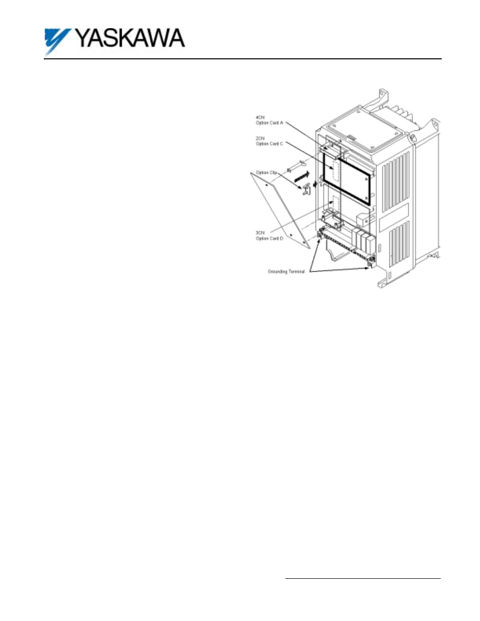
5. Option Card Installation: See Figure 1. Position the option card above the control board’s 2CN connector and
gently press the card into place.
6. Wiring: Refer to Figure 2 and Table 2. Make wire connections between the DI-08 card and drive as well as all
peripheral devices. Observe the following:
a) Keep DI-08 (i.e. control circuit) wiring separate from main circuit input/output wiring. A separate metallic
grounded conduit with only the option card’s wiring running through it is preferred.
b) To prevent erroneous operation caused by noise interference, use shielded cable for control signal
wiring. Limit the distance to 10m (33 feet) or less.
c) Route wires from the drive and connect to the peripheral device. Refer to the drive technical manual for further
information on use of shielded cable.
Important: The DI-08 input circuits can receive the output of relay contacts and transistors (open collector).
a) Use relays with highly reliable contacts (for very small current) with a rated voltage of 30VDC or more and a
rated current of 100mA or higher.
b) Use transistors (open collector) with a rated voltage of 35VDC or more and a rated current of 30mA or higher.
Figure 1. DI-08 Option Card Installation