Yaskawa DI-003 User Manual
Yaskawa Equipment
Yaskawa Electric America, Inc. – www.drives.com
IG.G7.68, Page 1 of 3
Date: 10/27/05, Rev: 05-10
120VAC Interface Option Card
DI-003
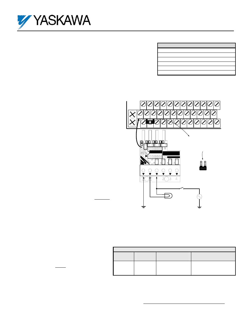
One channel shown as example, remaining channels are identical.
Figure 1. 120VAC Logic Input Option Card
TB3
Drive's I/O terminal
PE
Stanadard bare jumper to be
replaced with the insulated
one provided, in case of G7
upper row installation
S1
S2
S3
S4
S5
S6
S7
S8
SN
SC
SP
S9
S10
S11
S12
Switch/Control/PLC
AC Source,
120VAC
Monitoring Light
X2
X2
1
Part Number: DI-003 Kit (UTC000100 or UTC000064 Card)
Applicability: G7
Introduction: The 120VAC Logic Interface option card mounts directly to the
control terminal block on the drive and allows the use of 120VAC control logic
circuits as digital inputs to the drive (S9 - S12). Please check the note on Page 3
regarding power terminal strip interference.
To use all 12 inputs of the G7 (S1 - S12), this option card must be used in
conjunction with the DI-001 kit, which covers inputs (S1 - S8). Please refer to page 2 for details on installing the DI-003 kit in
conjunction with the DI-001 kit.
Receiving: All equipment is tested against defect at the
factory. Report any damages or shortages evident when
the equipment is received to the commercial carrier who
transported the equipment.
Warning: Hazardous voltage can cause severe injury or
death. Lock all power sources feeding the drive and the
option card’s wiring in the “OFF” position.
Important: Before installing this option, a technically
qualified individual, who is familiar with this type of
equipment and the hazards involved, should read this
entire installation guide.
Installation and Wiring:
1. Disconnect all electrical power to the drive.
2. Remove the drive’s front cover.
3. Verify that the “CHARGE” indicator lamp inside the
drive is off.
4. Use a voltmeter to verify that the voltage at the
incoming power terminals (L1, L2, L3) has been
disconnected.
5. Complete all main circuit terminal connections as the
installation of this board may block wiring access.
6. Complete all field wiring to the option card BEFORE
mounting the card to the drive. Follow this procedure
to prevent damage to the finger terminals of the
option card.
7. Connect the Neutral (common) of the command
signals to terminal X2 of the option card.
8. Connect the command signals to the desired
inputs of the option card. See example in Figure 1.
Important: Wires to the option card should be stripped
0.2” ± 20% for maximum system safety. Solder dipping
or ferrules are also highly recommended.
Important: For monitoring the input command signals,
optional pilot lights such as Neon modules can be
connected to the option card’s input terminals.
However, their Neutral MUST be connected to the
second (unused) X2 pin to avoid erroneous operation in
case of a wire break.
9. Remove the standard bare jumper between the drive’s I/O terminals SC and SP and replace it with the insulated jumper
included in the DI-003 kit.
Important: The provided insulated jumper will prevent any electrical and mechanical disturbances to the option card installation.
Table 1. General Specifications
Inputs: 4 + 2 Neutrals
Input Voltage: 120 VAC ± 15%, 57 - 63Hz
Input Impedance: 19 Kohm
Input Off Current: 4 mA
ON Response Time: 9 ms
OFF Response Time: 32 ms
Table 2. Terminal and Wire Specifications
Terminal
Symbol
Terminal
Screw
Clamping Torque
Lb-in (N-m)
Wire Range
AWG (mm
2
)
J1 M3
4.2 to 5.3
(0.5 to 0.6)
26 to 16
(Stranded: 0.14 to 1.5)
(Solid: 0.14 to 1.5)