Page 2 of 5 – Yaskawa iQpump1000 AC Drive User Manual
Page 2
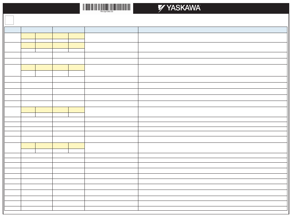
Step
4
Generic parameter setup for system with two or three pumps as boosters with or without pressure tank. Pumps will be lead & lag with 24hrs alternation. Start / Stop from the
keypad. Each drive has it’s own transducer.
Page 2 of 5
Yaskawa America, Inc., 2121 Norman Drive South, Waukegan, IL 60085, (800) YASKAWA (927-5292) Fax (847) 887-7310, [email protected], www.yaskawa.com, Document Number: TM.iQp1000.03 05/29/2014 © Yaskawa America, Inc.
Parameter
iQpump P1 Setting
iQpump P2 or higher
Description
Comments
b5-02
Pressure
Tank
No Pressure
Tank
Pressure
Tank
No Pressure
Tank
Proportional Gain Setting (P)
Increase proportional gain to make iQpump1000 more responsive. Caution: can cause instability if value is too high.
2.0
4.0
2.0
4.0
b5-03
Pressure
Tank
No Pressure
Tank
Pressure
Tank
No Pressure
Tank
PI Integral Time (I)
Decrease integral time to make iQpump1000 more responsive. Caution: can cause instability if value is too low.
3.0 sec.
2.0 sec.
3.0 sec.
2.0 sec.
C1-01
9.0 sec.
9.0 sec.
Acceleration Time 1
Time it takes to accelerate the pump motor from zero to maximum speed.
C1-02
5.0 sec.
5.0 sec.
Deceleration Time 1
Time it takes to decelerate the pump motor from maximum speed to zero.
C6-02
Centrifugal
Pump
Submersible
Pump
Centrifugal
Pump
Submersible
Pump
Carrier Frequency
Note: Please refer to the iQPump1000 manual for drive full load amp de-ratings if setting C6-02 carrier frequency selection other than 6 or 7
for drives above 40HP.
2
7
2
7
E2-01
Motor Nameplate Amps
Motor Nameplate Amps
Motor Rated Current
Set to the motor nameplate full load amps.
H5-01
1
P2 = 2, P3 = 3
Drive Node Address
P1-01
3
3
Pump Mode
Set drive software up for Memobus Multiplexing.
P1-03
XX PSI
XX PSI
Feedback Scaling
This should be the maximum range of the transducer output based on 4-20ma. If transducer is 300P SI that this is what should be
programmed in P1-03.
P1-04
-5 PSI
-5 PSI
Start-Draw down Level
Note: Make sure to see the "-" negative sign on display
P1-06
Centrifugal
Pump
Submersible
Pump
Centrifugal
Pump
Submersible
Pump
Minimum Pump speed
This should always be set based on where the pump curve starts working to overcome the head and system losses.
35.0 Hz
40.0 Hz
35.0 Hz
40.0 Hz
P1-08
XX PSI
XX PSI
Low Feedback Level
Low pressure fault should be set based on system. This is customer settings.
P1-09
25 sec.
25 sec.
Low Feedback Level Delay Time
P1-11
XX PSI
XX PSI
High Feedback Level
High Pressure fault should be set on average 20 PSI over the system set point.
P1-12
6 sec.
6 sec.
High Feedback Level Delay Time
P4-10
1
1
AUTO Mode Operator Run Power Down Storage
This allows drive to recover and automatically run after a loss of Utility Power if run (Auto) command is via keypad.
Warning: System will automatically restart.
P4-12
Centrifugal
Pump
Submersible
Pump
Centrifugal
Pump
Submersible
Pump
Trust Bearing Frequency
Thrust bearing frequency shout not be disabled when using a submersible pump motor.
0.0 Hz
30.0 Hz
0.0 Hz
30.0 Hz
P9-02
2
2
Feedback Source
System programmed for redundant transducer feedback. Each drive has its own transducer wired to A2.
P9-06
59.5 Hz
59.5 Hz
Lag Drive Fixed Speed
P9-08
2
2
Add Pump Mode
Sets the conditions for the lead pump drive so that the output speed must rise above P9-09 and the pressure to fall below P9-10 before add-
ing an additional pump to the system.
P9-09
59.5 Hz
59.5 Hz
Add Freq Level
Sets the system to stage on lag pump when lead pump is above P9-09 level and the system is 5PSI below Auto Set point.
P9-10
5.0 PSI
5.0 PSI
Add Delta Level
Sets the system to stage on lag pump when lead pump is above P9-09 level and the system is 5PSI below Auto Set point.
P9-11
14 sec.
14 sec.
Add Delay Time
Sets the time when the lag pump will stage on.. Adjust as needed for system operation.
P9-13
45.0 Hz
45.0 Hz
Remove Frequency Level
Sets the lag pump output frequency when it de-stages and goes back to a single lead pump. May have to adjust based on pump system
curve.
P9-15
5 sec
5 sec
Remove Delay Time
Sets the time when the lag pump will de-stage when speed falls below P9-13.
P9-18
98.0%
98.0%
High Feedback Quick De-stage
Allows program to this value when using High Pressure as Fault.
P9-25
2 for Duplex, 3 for Triplex
2 for Duplex, 3 for Triplex
Sets the maximum number of pumps in the
multiplex system.
Sets the number of pumps in the multiplex system.
Q1-01
XX PSI
XX PSI
System Setpoint
Note: Program this value last on the main keypad screen using Q1-01. U1-01 auto set point is the same as Q1-01.
iQpump1000 AC Drive
Multiplex Quick Start Procedure