H3-10 terminal a2 gain setting, Rbranch, Function: pi differential (setting: 16) – Yaskawa iQpump Controller Programming Manual User Manual
Page 90: Function: not used (setting: 1f)
90
YASKAWA
TM.iQp.07 iQpump Controller Programming Manual
Figure 1.82
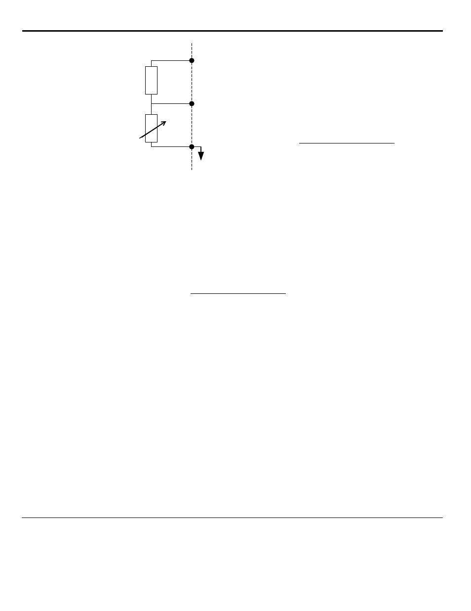
Figure 81. Thermistor to Drive Connection Diagram
After the connections are made, configure the A2 analog input for motor temperature protection by setting H3-09 = “E: Motor
Temperature”. Parameters L1-03, L1-04, and L1-05 set the response to the alarm level being exceeded, response to the fault level being
exceeded, and temperature sensing delay time, respectively.
The proper value of the branch resistance is approximated by the formula:
Where: (R
ptc@Tr
x 3) = The resistance value of the thermistor at either the alarm or fault level adjusted for three phase (three thermistors in
series, refer to typical PTC thermistor characteristic in
V
S
= The supply voltage (+15 Vdc)
V
ptc@OH3
= The rated voltage for the over-temperature alarm or fault
■
Function: PI Differential (Setting: 16)
Normal PI operation will adjust the iQpump drive output in order to match the measured feedback value to a desired setpoint. When PI is
operated in the differential mode, however, the iQpump drive output is adjusted in order to maintain a desired differential between two
feedback signals. Air handling unit return fan speed control in a “volume snatching” strategy for building pressure control is an example.
When the A2 analog input is configured as a PI Differential (H3-09 = “16: PI Differential”), the A1 analog input becomes the other PI
Differential input. The desired differential is set by parameter b5-07 (PI Differential Setpoint) and can be set so that A2 is held less than
A1 (b5-07 <0) or A2 is held greater than A1 (b5-07>0).
When PI Differential operation is chosen, the A1 feedback level can be monitored by U1-24 (PI Feedback) and the A2 feedback level can
be monitored by U1-53 (PI Feedback2).
■
Function: Not Used (Setting: 1F)
When H3-09 = “1F: Not Used,” any signal applied to the A2 analog input will be ignored by the drive.
◆
H3-10 Terminal A2 Gain Setting
Setting Range:
0.0 ~ 1000.0%
Factory Default: 100.0%
+V
(+15 V, 20 mA)
A2
(0-10 Vdc)
AC
PTC Thermistor
Branch resistance
18 k
Ω
*1
*1 The resistance value of 18 k
Ω is only valid for
using a 3-phase PTC with the characteristics shown in
the figure below.
above.
(R
ptc@Tr
x3) x (V
S
-V
ptc@OH3
)
V
ptc@OH3
Rbranch
=
Rbranch
=
(R
ptc@Tr
x3) x (V
S
-V
ptc@OH3
)
V
ptc@OH3