Installation guidelines valve operation, Friction loss chart (us psi) – Irritrol 100 Series User Manual
Page 2
!
Using pipe dope on valve connections can cause
thread damage and failure of the valve body.
Use only PTFE tape or pipe thread sealant.
• Note the flow direction arrows on the bonnet or body
and install accordingly.
• The valve can be installed at any angle without
affecting operation.
• The valve body plug and o-ring must be properly
installed in the unused inlet.
• Use direct-burial wire, utilizing different color codes
for each station control wire and one color for the
common wire to all valves.
• Waterproof wire splice connectors are absolutely
essential for proper electric control system operation.
Follow the installation instructions provided with the
connectors for optimum waterproof splice protection.
• Leaving a wire expansion loop at each valve location
on long-run wire lengths is recommended.
Installation Guidelines
Valve Operation
Flow Control
Flow control reduces the flow and pressure to valve outlet.
By turning the control handle clockwise, the flow will be
gradually reduced to zero.
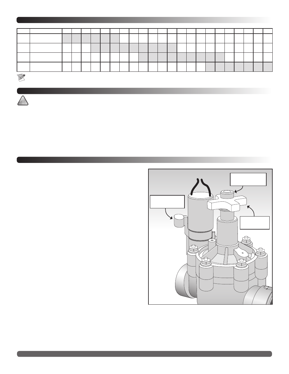
Internal Manual Bleed Knob
The internal manual bleed system is used to manually
operate the valve. Turning the internal bleed knob (located
beneath the solenoid) counterclockwise allows water to bleed
downstream from the diaphragm chamber. Internal pressure
is relieved from the top of the diaphragm, allowing the
valve to open. Turning the bleed knob clockwise until tight
shuts off the discharge enabling pressure to build within the
diaphragm chamber, causing the valve to close.
External Manual Bleed Knob (flush mode)
The external manual bleed knob, located on top of the flow
control handle, is used for system flushing. Turning this knob
counterclockwise allows water in the diaphragm chamber to
vent to atmosphere, creating maximum opening power and
debris flushing action. This operation bypasses the regulator
(if installed) and opens the valve fully, regardless of regulator
setting. In addition, the metering rod (attached to the
external bleed knob) can be easily removed for cleaning as
necessary.
©2014 Irritrol • www.irritrol.com • Technical Support: 1-800-634-8873
Form Number 1049501 Rev. C
Friction Loss Chart (US PSI)
GPM Flow
Size
Configuration
5
10 20 30 40 50 60 70 80 90 100 110 120 130 140 150 180 200 225 250 275 300
1”
globe
angle
6.3
6.3
4.2
4.2
3.2
3.1
4.1
2.7
7.2
4.8
10.9
7.9
1.5”
globe
angle
1.6
1.3
2.3
1.6
3.6
2.8
5.2
4.0
7.0
5.5
9.2
7.1
11.7
9.0
14.4
11.0
17.5
13.3
2”
globe
angle
2.1
1.2
2.7
1.6
3.3
2.0
4.0
2.4
4.8
2.8
5.6
3.3
6.5
3.9
7.5
4.4
8.05
5.1
3”
globe
angle
2.5
1.9
3.0
2.4
4.1
3.3
5.3
4.3
6.7
5.5
8.3
6.9
10.1
8.5
For optimum performance when designing a system, be sure to calculate total friction loss to ensure sufficient downstream pressure.
For optimum regulation performance, size regulating valves toward the higher flow ranges.
Internal Manual
Bleed Knob
Flow Control
Knob
External Manual
Bleed Knob