Jordan Valve Mark 58 Series – Globe Style Back Pressure Regulator User Manual
Ideal installation, I & m mark 58 series
3170 Wasson Road • Cincinnati, OH 45209 USA
Phone 513-533-5600 • Fax 513-871-0105
[email protected] • www.jordanvalve.com
I & M Mark 58 Series
Installation & Maintenance Instructions for
Mark 58 Back Pressure Regulating & Relief Valve
Warning: Jordan Valve back pressure regulators must only be used, installed and repaired in accordance with these
Installation & Maintenance Instructions. Observe all applicable public and company codes and regulations. In the
event of leakage or other malfunction, call a qualified service person; continued operation may cause system failure
or a general hazard. Before servicing any valve, disconnect, shut off, or bypass all pressurized fluid. Before disas-
sembling a valve, be sure to release all spring tension.
Please read these instructions carefully!
Your Jordan Valve product will provide you with long,
trouble-free service if it is correctly installed and main-
tained. Spending a few minutes now reading these in-
structions can save hours of trouble and downtime later.
When making repairs, use only genuine Jordan Valve
parts, available for immediate shipment from the factory.
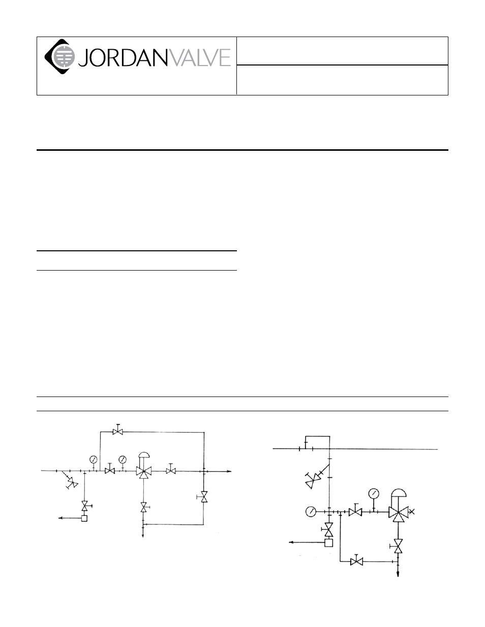
Ideal Installation
To protect the valve from grit, scale, thread chips,
1.
and other foreign matter, all pipe lines and piping
components should be blown out and thoroughly
cleaned before the valve is installed.
Shutoff valves, pressure gauges, and bypass piping
2.
should be installed as indicated in the diagram to
provide easier adjustment, operation, and testing.
A line strainer should be installed on the inlet side of
3.
the regulator to protect it from grit, scale and other
foreign matter. A 0.033 perforated screen is usually
suitable. Line strainers are available from Jordan Valve.
For best control, 3’0” straight sections of pipe should
4.
be installed on either side of the valve.
Install the regulators in the highest horizontal line of
5.
piping to provide drainage for inlet and outlet pip-
ing, to prevent water hammer, and to obtain faster
regulation.
The regulator may be installed in a flow-through
6.
manner as in Figure 1 or into a tee off of the main
line (with one port plugged) as shown in Figure 2.
Flow may be in either direction through the body of
the regulator. Bypassed fluid exits out of the bottom
bypass port.
In hot vapor lines, upstream and downstream piping
7.
near the regulator should be insulated to minimize
condensation.
Expand the outlet piping at least one pipe size if the
8.
outlet pressure (downstream) is 25% of the inlet
pressure or less. As standard tapered expander con-
nected to the outlet of the regulator is recommend-
ed. Minimizing bypass piping length and number of
elbows will improve valve performance by reducing
pressure buildup.
Where surges are severe, a piping accumulator is
9.
recommended.
Condensate
Return
6
1 Inlet shut-off valve
2 MK 58 BPRV
3 Strainer and Drain Valve
4 Pressure Gauge
Ideal Installation
4
4
2
1
6
7
5
3
Main Line
Main Line
Condensate
Return
By Pass
3
6
5
1
4
2
7
4
8
By Pass
5 Steam trap and valve
6 Manual bypass valve
7 Bypass shut-off valve
8 Pipe plug