Jordan Valve Mark 5108 Series Back Pressure Regulator User Manual
I & m mark 5108 series, Ntroduction
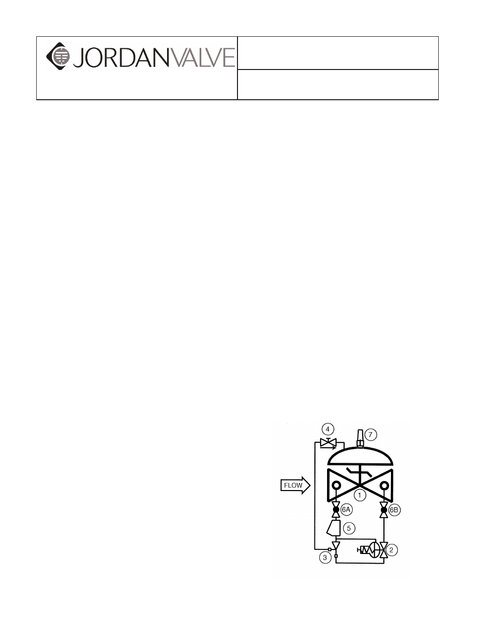
4.
Flow Control Valve,
a needle-type valve
which provides adjustable, restricted flow in
one direction, and free flow in the opposite
direction. On the Mark 5108, the flow control
valve is connected as a closing speed
control.
5.
The Y-Strainer (standard on water
service valves) or Mark 5123 Inline Strainer
(standard on fuel service valves). The strainer
protects the pilot system from solid
contami nants in the line fluid.
6.
Two Ball Valves (standard on water service
valves, optional on fuel service valves), useful
for isolating the pilot system for maintenance
or trouble shooting.
At user option, the 5108 may also be equipped with
the following:
1.
Visual Indicator.
2.
Limit Switch Assembly (includes visual
indicator).
3.
Opening Speed Control.
I
ntroductIon
The Mark 5108 may be generically described as
a back pressure control valve, i.e., it controls the
pressure at its inlet. With this type of control, the
Mark 5108 may be employed in two different ways:
1.
As a Pressure Relief Valve
. Here the 5108
is installed on a bypass from a main line. It
opens to relieve any pressure above its set
point.
2.
As a Pressure Sustaining Valve
. Here the
Mark 5108 is installed in the main line itself. It
functions to control the incoming pressure at
the set point, or more commonly, to prevent
the pressure from falling below a
predetermined minimum. For example, it may
be installed on the discharge of a pump to
ensure that the pump remains "on its curve."
The Mark 5108 consists of the following components,
arranged as shown on the schematic diagram:
1.
Basic Control Valve
, a hydraulically
operated, diaphragm-actuated, globe or
angle valve which closes with an elastomer-on-
metal seal.
2.
Pressure Relief Pilot,
a two-way, normally
closed pilot valve which senses up-stream
presure under its diaphragm and balances it
against an adjustable spring load. An increase
in upstream pressure tends to make the pilot
open.
3.
Ejector
, a simple "tee" fitting with a fixed orifice
in its inlet port. It provides the proper pressure to
the diaphragm chamber of the main valve
depending on the position of the pressure relief
pilot.
3170 Wasson Road • Cincinnati, OH 45209
Phone 513.533.5600 • Fax 513.871.0105 (f)
[email protected] • www.jordanvalve.com
I & M Mark 5108 Series
Installation & Maintenance Instructions for the
Mark 5108 Back Pressure Regulating Valve
Warning: Jordan Valve Control Valves must only be used, installed and repaired in accordance with these Installa-
tion & Maintenance Instructions. Observe all applicable public and company codes and regulations. In the event
of leakage or other malfunction, call a qualified service person; continued operation may cause system failure or
a general hazard. Before servicing any valve, disconnect, shut off, or bypass all pressurized fluid. Before disassem-
bling a valve, be sure to release all spring tension.