Jordan Valve Mark 508 Series – Tank Blanketing Valve User Manual
Installation, Start-up procedure, Maintenance
3170 Wasson Road • Cincinnati, OH 45209 USA
Phone 513-533-5600 • Fax 513-871-0105
[email protected] • www.jordanvalve.com
I & M Mark 508 (1½” & 2”)
Installation & Maintenance Instructions for
Mark 508 Back Pressure Regulators
Warning: Jordan Valve Pressure Regulators must only be used, installed and repaired in accordance with these In-
stallation & Maintenance Instructions. Observe all applicable public and company codes and regulations. In the event
of leakage or other malfunction, call a qualified service person; continued operation may cause system failure or a
general hazard. Before servicing any valve, disconnect, shut off, or bypass all pressurized fluid. Before disassembling
a valve, be sure to release all spring tension.
Please read these instructions carefully!
Your Jordan Valve product will provide you with long-
term, trouble-free service if it is correctly installed.
Spending a few minutes of your time reading these in-
structions now may save hours of trouble and downtime
later.
Installation
piping to provide drainage for inlet and outlet pip-
ing, and to obtain faster regulation.
6.
The flow arrow on the regulator body must be
pointed in the direction of flow. The regulator may
be installed vertically or horizontally without affect-
ing its operation.
7.
For best control, 3’ 0” straight sections of pipe
should be installed on either side of the regulator.
Start-Up Procedure
With the inlet and outlet shutoff valves closed:
1.
Throttle the bypass valve so that the pressure to be
controlled is maintained near the seat point.
2.
Slowly open the inlet shutoff valve.
3.
Open the outlet shutoff valve.
4.
Slowly close the bypass valve, but do not close it
fully until you are certain that the regulator has con-
trol of the system.
5.
To change the controlled pressure, turn the adjust-
ing screw clockwise to increase pressure, counter-
clockwise to decrease pressure.
Maintenance
Caution: Make certain that there is no pressure in the
valve before loosening any fittings or joints. The fol-
lowing steps are recommended:
1.
Close inlet shutoff valve.
2.
Allow pressure to bleed of through downstream
piping. Do not cause a reverse flow through valve
by bleeding pressure from upstream side of valve.
3.
When downstream pressure gauge indicates no
pressure in the line, close the outlet shutoff valve.
Replacing the Main Diaphragm
1.
Remove the closing cap (1).
2.
Thread the adjusting screw (2) out of the spring
tube.
3.
If the set range is in psi, remove the spring guide.
4.
Remove range spring (3).
1.
To protect the regulator from grit, scale, thread
chips, and other foreign matter, all pipe lines and
piping components should be blown out and thor-
oughly cleaned before the regulator is installed.
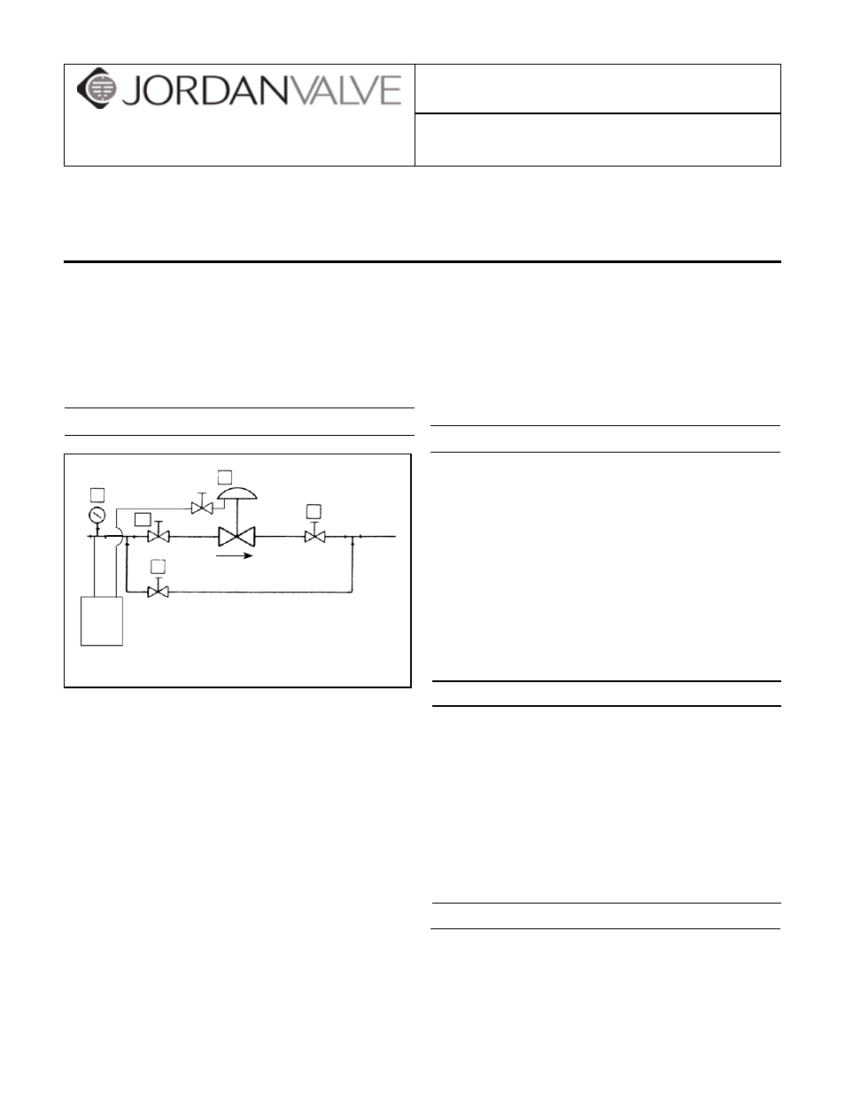
2.
Shut-off valves, pressure gauges, and by-pass
piping should be installed as indicated in the
diagram to provide easier adjustment, operation,
and testing.
3.
In preparing threaded pipe connections, care
should be exercised to prevent pipe sealing com-
pound from getting into the pipe lines. Pipe sealing
compound should be used sparingly, leaving the
two lead threads clean. Jordan uses, and recom-
mends, thread sealer Teflon ribbon.
4.
A 3/4” control line should be connected to this
actuator lower case if used for vapor recovery. Oth-
erwise, leave plug in place.
5.
Install the regulators in the highest horizontal line of
4
1
5
1
1
2
1. Shut-off valve - full port
2. Control line (when used)
4. Pressure gauge
5. MK508 back pressure regulator
Tank
or Gas
Source
By-pass