Jordan Valve Mark 608BP - Balanced Plug Regulator User Manual
I & m mark 608bp, Ideal installation, Sizing
3170 Wasson Road • Cincinnati, OH 45209 USA
Phone 513-533-5600 • Fax 513-871-0105
[email protected] • www.jordanvalve.com
I & M Mark 608BP
Installation & Maintenance Instructions for
Mark 608BP Gas Pressure Regulators
Warning: Jordan Valve Pressure Regulators must only be used, installed and repaired in accordance with these In-
stallation & Maintenance Instructions. Observe all applicable public and company codes and regulations. In the event
of leakage or other malfunction, call a qualified service person; continued operation may cause system failure or a
general hazard. Before servicing any valve, disconnect, shut off, or bypass all pressurized fluid. Before disassembling
a valve, be sure to release all spring tension.
Please read these instructions carefully!
Your Jordan Valve product will provide you with long,
trouble-free service if it is correctly installed and main-
tained. Spending a few minutes now reading these in-
structions can save hours of trouble and downtime later.
When making repairs, use only genuine Jordan Valve
parts, available for immediate shipment from the factory.
Ideal Installation
1.
To protect the regulator from grit, scale, thread
chips and other foreign matter, ALL pipelines and
piping components should be blown out and thor-
oughly cleaned before the installation process be-
gins.
2.
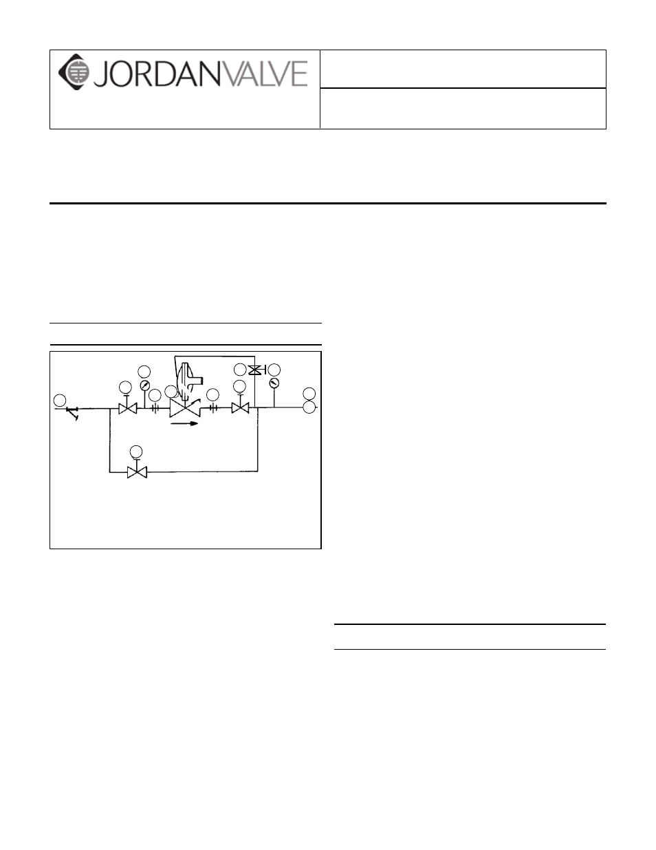
Shutoff valves, pressure gauges and by-pass piping
should be installed as indicated in the Installation
Schematic to provide easier adjustment, operation,
and testing.
3.
In preparing threaded pipe connections, care
should be exercised to prevent pipe sealing com-
pound from getting into the pipe lines. Pipe sealing
compound should be used sparingly, leaving the
two end threads clean. Jordan recommends Teflon
tape.
4.
A line strainer should be installed on the inlet side
of the regulator to protect pipe from grit, scale and
other foreign matter. A 0.033 perforated screen is
usually suitable for this purpose. Line strainers are
available from Jordan Valve.
5.
The flow arrow on the regulator body must be
pointed in the direction of flow. The regulator may
be installed in any position. The actuator may be
rotated to any position relative to the body (see siz-
ing.) Loosen the union nut and position the actua-
tor. Pull the union nut up hand-tight, then tighten ¼
turn. (The union nut is 8-sided and may be used as
a guide.)
6.
Provisions are provided to vent the case from the
top or bottom by a ¼” pipe tap opening. One open-
ing is plugged, the other has a screened (bug) vent.
Reverse these if it is desired open vents should
point downward; a street elbow can be used if
needed. Some installations will require that this
vent be piped to some location external to the
regulator. When remote piping is used, ¼” size is
adequate. NEVER BLOCK OFF THE VENT LINE. Fol-
low local regulations.
7.
Install a relief valve downstream from the regulator
to protect downstream components from over-
pressurization. Generally, the setting of the relief
valve should be at least 20% greater than the regu-
lator set point. It must have adequate flow capacity
to protect the downstream components should the
regulator fail to shut off.
8.
Operate the regulator within its rated pressure and
temperature. The standard Mark 608BP is rated
at 150 psig max (inlet or outlet section) at -20 to
+200°F. Regulator ratings and materials of con-
struction are listed on the valve name plate.
Sizing
Refer to the sizing charts for the flow capacity of the
regulator under various conditions.
Because of the weight of the diaphragm assembly and
friction in the moving parts, there is a difference in the
lowest setpoint attainable when the actuator housing is
upright, or inverted. (Upright refers to the spring hous-
ing cap pointing vertically up.) Lower set points can be
achieved with the housing inverted.
With this information, refer to the flow capacity chart in
By-Pass Line
1. Shut off Valve
2. Pipe Union
3. Strainer and Drain Valve
4. Pressure Gauge
5. Jordan Regulator
6. Relief Valve
7. Sensing Line
3
1
6
4
1
2
5
2
4
1
R
7