Jordan Valve Mark 630 Series - Gas Service/High Pressure Regulator User Manual
I & m mark 630, Installation
3170 Wasson Road • Cincinnati, OH 45209 USA
Phone 513-533-5600 • Fax 513-871-0105
[email protected] • www.jordanvalve.com
I & M Mark 630
Installation & Maintenance Instructions for
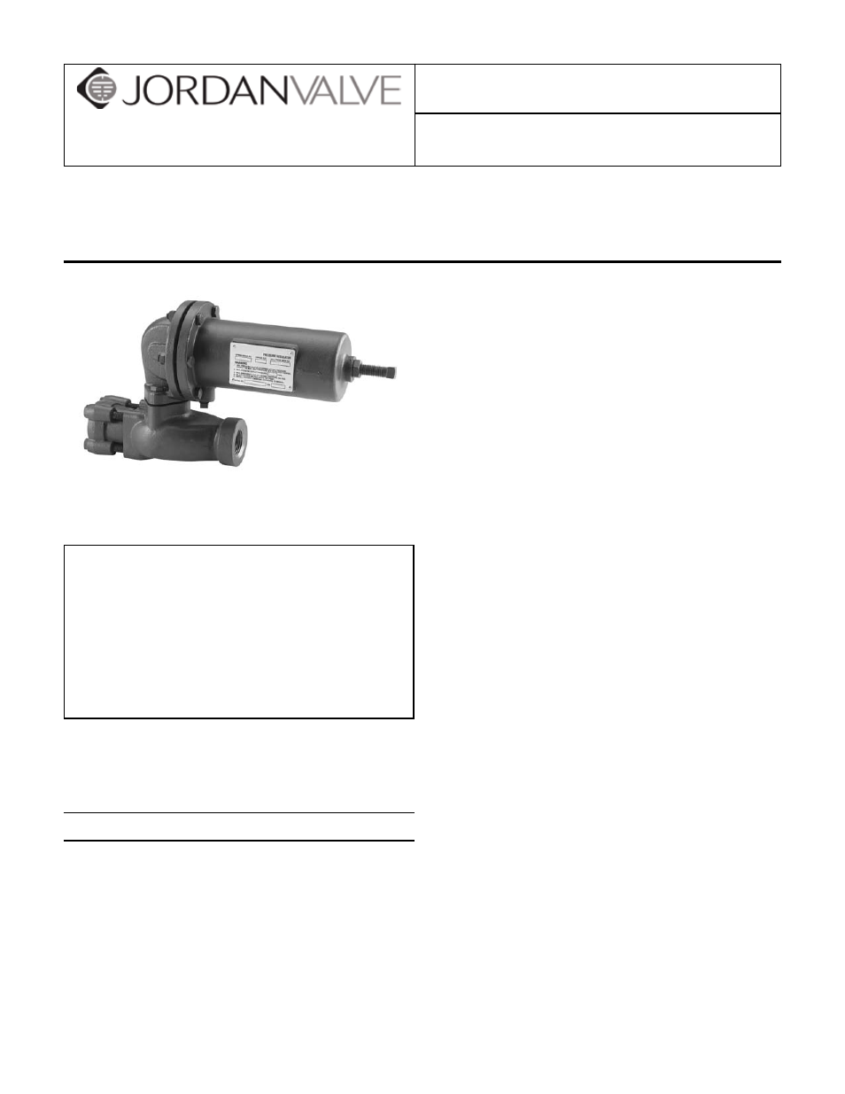
Mark 630 High Pressure Regulator
Warning: Jordan Valve Pressure Regulators must only be used, installed and repaired in accordance with these In-
stallation & Maintenance Instructions. Observe all applicable public and company codes and regulations. In the event
of leakage or other malfunction, call a qualified service person; continued operation may cause system failure or a
general hazard. Before servicing any valve, disconnect, shut off, or bypass all pressurized fluid. Before disassembling
a valve, be sure to release all spring tension.
Note: This document is to be used in conjunction with
Mark 630 Series Cut Sheet.
WARNING! Over-pressure of this regulator or
installation of the regulator in applications which
may see pressure levels beyond those for which
the regulator is designed may result in leakage
and/or catastrophic failure. This failure could
result in leaking gas, damage to surrounding
equipment, personal injury or death. To prevent
such damage/injury the regulator should be in-
stalled in a safe location and should be chosen
based upon the user’s specific application.
It is highly recommended that suitable pressure relieving
devices, as recommended by appropriate codes or stan-
dards, be installed in your system to assure that maxi-
mum rated pressures are not exceeded.
Installation
The Mark 630 should be chosen based upon the
1.
maximum inlet pressures, pressure drops and out-
let pressures as described in Table 1 and 2. Flow
capacities are listed in Table 4. The operating tem-
perature range is -20°F to 150°F. When choosing
and installing a regulator one must ensure that the
conditions do not exceed these parameters. Fur-
thermore, large differentials in pressure across the
regulator may result in the formation of ice in the
orifice area. The resulting decrease in orifice area
may affect the regulators ability to flow in sufficient
volume for downstream demand. Therefore, large
pressure drop applications may require the use of
more than one regulator.
Make sure that line pressure has been eliminated
2.
prior to the installation of any regulator. Prior to
installation the line should be inspected to ensure
that there is no debris that might damage the regu-
lator. Install regulator with properly sized threaded
connections and utilizing thread sealant.
The regulator should be installed with the flow ar-
3.
row on the side of the body in the correct orienta-
tion to flow - i.e. higher pressure upstream, lower
regulated pressure downstream. As is true with
most regulators, the Mark 630 has an outlet pres-
sure rating that is less than the inlet pressure rating.
Overpressure protection must be provided to avoid
over-pressure condition if the actual inlet pressure
can exceed the outlet pressure rating. Refer to Ta-
bles 1 and 2 for maximum inlet pressures, pressure
drops and outlet pressure ranges.
The regulator may be installed in any orientation
4.
as long as the flow is in proper agreement with
the flow arrow on the side of the body. However,
the regulator should be positioned such that the
screened breather (24) will not collect debris or
moisture.
Vent Line Option
The Mark 630 includes a vent or Breather (24) in the
Spring Housing (3). If there is concern about build-up
of gas in a confined location, the Breather may be re-
moved to allow installation of a remote vent line. With the
Breather removed, a vent line may be installed into the
¼” NPT port. This vent line should be as large a diameter
as possible and should utilize minimal bends and el-
bows. Furthermore, the vent line opening should be pro-
tected from weather or debris and should be checked
regularly for blockage.