Jordan Valve Mark 686 Series – Air Loaded Globe Regulator User Manual
I & m mark 686 series, Ideal installation, Preferred installation
3170 Wasson Road • Cincinnati, OH 45209 USA
Phone 513-533-5600 • Fax 513-871-0105
[email protected] • www.jordanvalve.com
I & M Mark 686 Series
Installation & Maintenance Instructions for
Mark 686 Pressure Regulators (1/4” – 2”)
Warning: Jordan Valve pressure regulators must only be used, installed and repaired in accordance with these In-
stallation & Maintenance Instructions. Observe all applicable public and company codes and regulations. In the event
of leakage or other malfunction, call a qualifi ed service person; continued operation may cause system failure or a
general hazard. Before servicing any valve, disconnect, shut off, or bypass all pressurized fl uid. Before disassembling
a valve, be sure to release all spring tension.
Please read these instructions carefully!
Your Jordan Valve product will provide you with long,
trouble-free service if it is correctly installed and main-
tained. Spending a few minutes now reading these in-
structions can save hours of trouble and downtime later.
When making repairs, use only genuine Jordan Valve
parts, available for immediate shipment from the factory.
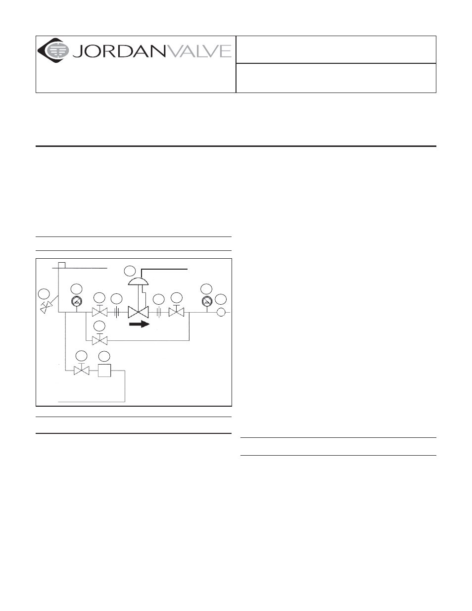
Ideal Installation
Main Steam Line
1 Shut off Valve
2 Pipe Union
3 Strainer and Drain Valve
4 Pressure Gauge
5 Jordan Regulator
6 Relief Valve
7 Steam Trap
4
R
4
1
2
2
1
3
5
7
1
1
6
Air Signal
Preferred Installation
To protect the valve from grit, scale, thread chips,
1.
and other foreign matter, all pipe lines and piping
components should be blown out and thoroughly
cleaned before the valve is installed.
Shutoff valves, pressure gauges, and bypass piping
2.
should be installed as indicated in the Ideal Installa-
tion Schematic to provide easier adjustment, opera-
tion, and testing.
In preparing threaded pipe connections, care
3.
should be exercised to prevent pipe sealing com-
pound from getting into the pipe lines. Pipe sealing
compound should be used sparingly, leaving the
two end threads clean. Jordan uses, and recom-
mends, thread sealer Tefl on ribbon.
A line strainer should be installed on the inlet side of
4.
the regulator to protect it from grit, scale and other
foreign matter. A 0.033 perforated screen is usu-
ally suitable. Line strainers are available from Jordan
Valve.
Install the regulator in the highest horizontal line of
5.
piping to provide drainage for inlet and outlet piping,
to prevent water hammer and to obtain faster regula-
tion.
The fl ow arrow on the regulator body must be
6.
pointed in the direction of fl ow. The regulator may be
installed vertically or horizontally without affecting its
operation.
For best control, 3’0” straight sections of pipe
7.
should be installed on either side of the valve.
In hot vapor lines, upstream and downstream
8.
piping near the regulator should be insulated to
minimize condensation.
If possible, install a relief valve downstream from the
9.
valve. Set at 15 psi above the control point of the
regulator.
Expand the outlet piping at least one pipe size if
10.
the controlled pressure (downstream) is 25% of
the inlet pressure or less. A standard tapered ex-
pander connected to the outlet of the regulator is
recommended.
Where surges are severe, a piping accumulator is
11.
recommended.
Operate the regulator within its rated pressure and
12.
temperature.
Start-Up
Fully open the outlet shut-off valve.
1.
Slowly open the inlet shut-off valve.
2.
Slowly open and close outlet shut-off valve several
3.
times. This fully strokes the valve to insure satisfac-
tory operation.
With outlet shut-off valve open, slowly increase the
4.
air signal until the desired pressure is shown on the
outlet pressure gauge.
To increase the controlled pressure, increase the
5.
air signal. Note that the air signal will have to be
slightly greater than the desired set point.