Jordan Valve Mark 695 Series - Piloted Tank Blanketing Regulator User Manual
I & m mark 695 series, Ideal installation, Control line
Please read these instructions carefully!
Your Jordan Valve product will provide you with
long, trouble-free service if it is correctly installed
and maintained. Spending a few minutes now read-
ing these instructions can save hours of trouble and
downtime later.
When making repairs, use only genuine Jordan Valve
parts, available for immediate shipment from the fac-
tory.
3170 Wasson Road • Cincinnati, OH 45209
Phone 513.533.5600 • Fax 513.871.0105 (f)
[email protected] • www.jordanvalve.com
I & M Mark 695 Series
Installation & Maintenance Instructions for the
Mark 695 Internally Piloted Tank Blanketing Valve
Warning: Jordan Valve Pressure Regulators must only be used, installed and repaired in accordance with these
Installation & Maintenance Instructions. Observe all applicable public and company codes and regulations. In the
event of leakage or other malfunction, call a qualified service person; continued operation may cause system failure
or a general hazard. Before servicing any valve, disconnect, shut off, or bypass all pressurized fluid. Before disas-
sembling a valve, be sure to release all spring tension.
-1-
Ideal Installation
1. To protect the valve from grit, scale, thread
chipsand other foreign matter, ALL pipelines
and pipingcomponents should be blown out and
thoroughly cleaned before the installation process
begins.
2. Shutoff valves, pressure gauges and by-pass piping
are optional, and if installed should be in accordance
with all applicable codes, standards, and practices.
They are recommended to provide easier adjustment,
operation, and testing.
3. The flow arrow on the valve body must be pointed
in the direction of flow. Ideally, the valve should be
installed in the highest horizontal line of piping.
4. Install the relief valve on the tank. Set above the
control point of the valve but below the maximum
safety limit for the tank.
5. It is strongly recommended that the installer read
and be thoroughly familiar with API 2000, Standard
Information for Tank Blanketing Regulator Selection
before installing and attempting to operate this
product.
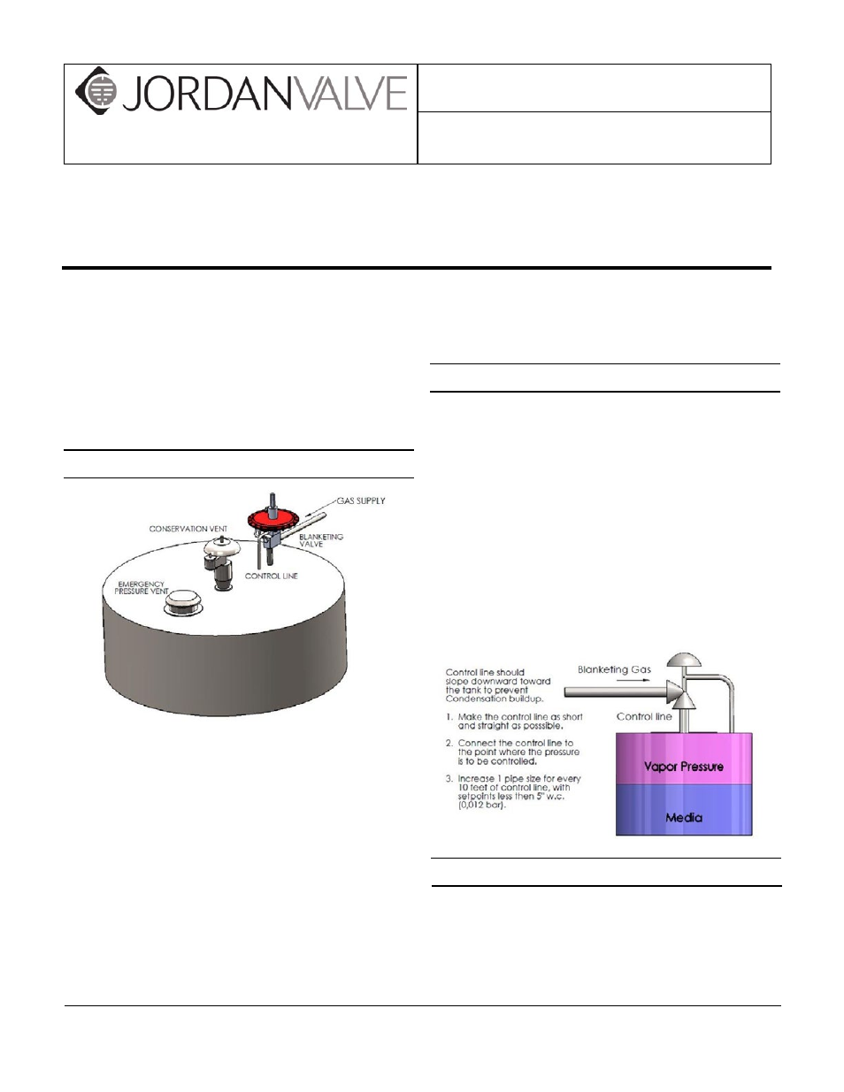
Control Line
A control line must be installed as follows:
1. Connect one end of a 3/8” tube to the fitting on the
bottom of the main valve actuator.
2. Connect the other end to an appropriate fitting on
the tank.
3. DO NOT locate the control line tap in any location
where turbulence or abnormal velocities may occur.
4. The control line should be sloped away from the
valve.
5. Install a pressure gauge to measure pressure in the
tank itself, not in the outlet piping or the control line
to aid in setting the valve.
Control Line Piping Recomendation
•
Keep the regulator as close to the tank as possible
and as high as possible.
•
Minimize the length of the downstream pipe coming
from the valve.