Jordan Valve Mark 82 Series – Internal Piloted Temperature Regulator User Manual
I & m mark 82, Installation, Bulb installation
3170 Wasson Road • Cincinnati, OH 45209 USA
Phone 513-533-5600 • Fax 513-871-0105
[email protected] • www.jordanvalve.com
I & M Mark 82
Installation & Maintenance Instructions for
Mark 82 Temperature Regulators
Warning: Jordan Valve Temperature Regulators must only be used, installed and repaired in accordance with these
Installation & Maintenance Instructions. Observe all applicable public and company codes and regulations. In the event
of leakage or other malfunction, call a qualifi ed service person; continued operation may cause system failure or a
general hazard. Before servicing any valve, disconnect, shut off, or bypass all pressurized fl uid. Before disassembling a
valve, be sure to release all spring tension.
Please read these instructions carefully!
Your Jordan Valve product will provide you with long-term,
trouble-free service if it is correctly installed. Spending a
few minutes of your time reading these instructions now
may save hours of trouble and downtime later.
Installation
To protect the temperature regulator from grit, scale,
1.
thread chips, and other foreign matter, all pipe lines
and piping components should be blown out and
thoroughly cleaned before the temperature regula-
tor is installed.
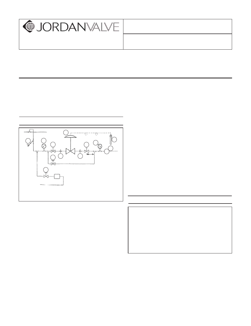
Shutoff valves, pressure gauges, and bypass piping
2.
should be installed as indicated in the diagram to
provide easier adjustment, operation and testing.
In preparing threaded pipe connections, care should
3.
be taken to prevent pipe sealing compound from
getting into the pipe lines. Pipe sealing compound
should be used sparingly, leaving the two lead
threads clean.
A line strainer should be installed on the inlet side
4.
of the temperature regulator to protect it from grit,
scale and other foreign matter. A 0.033 perforated
screen is usually suitable. Line strainers are avail-
able from Jordan Valve.
Install the regulator in the highest horizontal line of
5.
piping to provide drainage for inlet and outlet pip-
ing, to prevent water hammer, and to obtain faster
regulator.
The fl ow arrow on the regulator body must be point-
6.
ed in the direction of the fl ow. The regulator may be
installed vertically or horizontally without affecting its
operation.
For best control, 3’ 0” straight sections of pipe should
7.
be installed on either side of the regulator.
Upstream and downstream piping near the regulator
8.
should be insulated to minimize condensation in hot
vapor lines.
For injection heating applications, the regulator
9.
should be installed above the maximum water level
in the tank, or a check valve should be installed to
prevent water from backing up into the regulator.
For best regulation, the temperature regulator
10.
should be installed as closely as possible to the unit
in which the temperature is being controlled.
On steam control applications, install a steam trap
11.
of suffi cient capacity to drain the coil or condenser.
Be sure to have a good fall to the trap, and no back
pressure. Best control is obtained when the coil or
condenser is kept dry.
Bulb Installation
The Thermal System is a hermetically sealed unit
consisting of a sensing bulb, capillary tubing, pro-
tective armor, and actuator assembly. This unit
contains the thermostatic charge that operates
the temperature regulator. Please do not tamper
with it. In case the charge is lost, the thermal
system must be replaced as a complete unit. It is
not repairable in the fi eld and must be returned
to the factory for repairs.
Correct Installation – For effective temperature con-
1.
trol, correct installation of the sensing bulb is essen-
tial. For best results, the bulb should be installed
at a point of true representative temperature and
where there is good circulation. A thermometer or
other temperature sensing device (if used) should
be placed as close as possible to the sensing bulb
of the regulator.
Handle the capillary and armor carefully so they are
2.
not crushed, kinked or twisted. A bend of 4½” ra-
1. Shut-Off Valve
2. Pipe Union
3. Strainer & Drain Valve
4. Pressure Gauge
5. Jordan Regulator
6. Relief Valve
7. Thermal Bulb
Main Steam Line
By-Pass Line
Return Line
Condensate
Steam
Trap
3
1
1
2
2
7
6
R
4
1
5
1
4