Chapter 2, Motherboard information – Lanner FW-7582 User Manual
Page 16
12
Motherboard Information
Chapter 2
Network Application Platforms
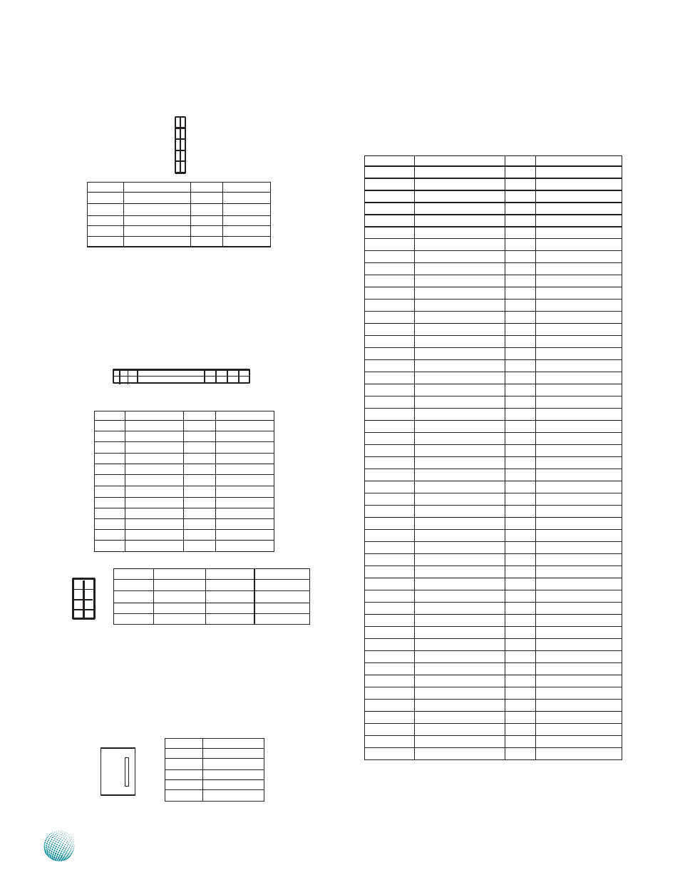
ATX Power Connector(ATX1, ATX2): These 24-pin and
8-pin connectors are for connecting ATX power supply
plugs. Find the proper orientation when inserting the
plugs, for the supply plugs are designed to fit these
connectors in only one orientation.
CPU Fan Connectors (CON1/CON2/CON3/CON4): 4-pin
connector for connecting the fans to be monitored with
the smart fan control. Connect CPU fan 0 and 1 to CON3
and CON4 respectively; connect SYS fan to CON 1 and
connect AUX fan to CON2. See H/W monitor setting in the
BIOS menu.
Pin No.
Function
1
SYSFANOUTPWM
2
NC
3
SYSFANIN
4
VFAN1
5
Ground
Pin No.
Pin name
Pin No.
Pin name
1
+3.3V
2
+3.3V
3
+3.3V
4
-12V
5
Ground
6
Ground
7
+5V
8
PSON-
9
Ground
10
Ground
11
+5V
12
Ground
13
Ground
14
Ground
15
Power Good
16
NC
17
StandBy 5V
18
+5V
19
+12V
20
+5V
21
+12V
22
+5V
23
+3.3V
24
Ground
Pin No.
Pin name
Pin No.
Pin name
1
Ground
2
+12V
3
Ground
4
+12V
5
Ground
6
+12V
7
Ground
8
+12V
Pin No.
Function
Pin No.
Function
1
CLK_33M_P80
2
LPC_LAD1
3
RST_80DGPT_N
4
LPC_LAD0
5
LPC_FRAME_N
6
+3.3V
7
LPC_LAD3
8
Ground
9
LPC_LAD2
10
Ground
1 23
2 24
CPU Socket: The LGA 1155 socket is for connecting the
CPU.
PCIEC1: PCI Express x8 Connectors with PCIEx8 mode
Pin No.
Function
Pin No.
Function
B1
+12V
A1
PRSNT1#
B2
+12V
A2
+12V
B3
+12V
A3
+12V
B4
GND
A4
GND
B5
SMCLK
A5
JTAG2
B6
SMDAT
A6
JTAG3
B7
GND
A7
JTAG4
B8
+3.3V
A8
JTAG5
B9
JTAG1
A9
+3.3V
B10
3.3VAUX
A10 +3.3V
B11
WAKE#
A11 PERST#
B12
BYPASS0 Mode
A12 GND
B13
GND
A13 REFCLKA+
B14
CPUPETP0
A14 REFCLKA-
B15
CPUPETN0
A15 GND
B16
GND
A16 CPUPERP0
B17
LANM0_LATCH_H A17 CPUPERN0
B18
GND
A18 GND
B19
CPUPETP1
A19 BYPASS1 Mode
B20
CPUPETN1
A20 GND
B21
GND
A21 CPUPERP1
B22
GND
A22 CPUPERN1
B23
CPUPETP2
A23 GND
B24
CPUPETN2
A24 GND
B25
GND
A25 CPUPERP2
B26
GND
A26 CPUPERN2
B27
CPUPETP3
A27 GND
B28
CPUPETN3
A28 GND
B29
GND
A29 CPUPERP3
B30
REFCLK1A+
A30 CPUPERN3
B31
REFCLK1A-
A31 GND
B32
GND
A32 LANM1_LATCH_H
B33
CPUPETP4
A33 LANM1_LATCH_L
B34
CPUPETH4
A34 GND
B35
GND
A35 CPUPERP4
B36
GND
A36 CPUPERN4
B37
CPUPETP5
A37 GND
B38
CPUPETN5
A38 GND
B39
GND
A39 CPUPERP5
B40
GND
A40 CPUPERN5
B41
CPUPETP6
A41 GND
B42
CPUPETN6
A42 GND
B43
GND
A43 CPUPERP6
B44
GND
A44 CPUPERN6
B45
CPUPETP7
A45 GND
B46
CPUPETN7
A46 GND
B47
GND
A47 CPUPERP7
B48
LANM0_LATCH_L A48 CPUPERN7
B49
GND
A49 GND
2
4
6
8
1
3
5
7
1 2 3 4 5
1
9
2
10