Lanzar VIBE286 User Manual
Page 3
V i b e r a n t O w n e r ’ s M a n u a l - 3
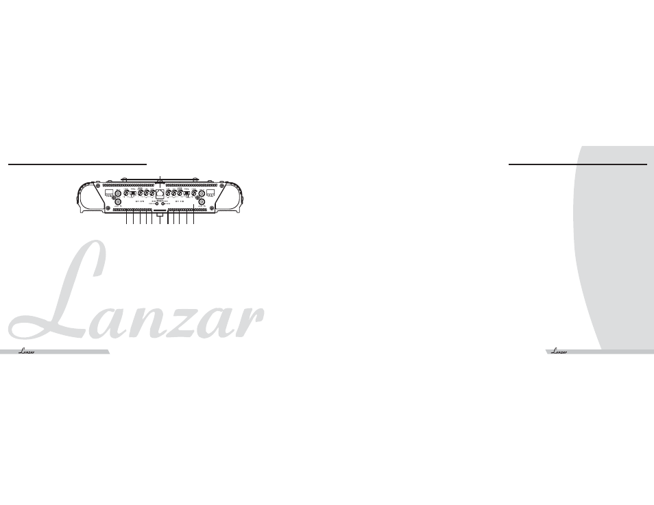
1. REMOTE BASS BOOST
Plug in the remote bass boost control wire in here
2. INPUT LEVEL CONTROLS
Enables the matching of input levels to the output levels from
head unit (or other signal source).
3. CROSSOVER MODE SELECTOR
Determines the mode of built-in crossover:
low pass (permits only low frequency signals to pass to speakers),
high pass (permits only high frequency signals to pass to speakers),
or flat.
4. BASS BOOST CONTROL
With a bass boost switch engaged, the bass level is increased
approx 18dB.
5. POWER & PROTECTION INDICATORS
Provide instant information on status of amplifier, including
short-circuit and thermal overload alerts.
6. HIGH PASS FILTER (HPF)
When Crossover Mode Selector is in High Pass Mode, this control
limits the frequencies which will be distributed to the speakers
to those below the value to which this is set within the range 80-
2.5KHz.
7. LOW PASS FILTER (LPF)
When Crossover Mode Selector is in Low Pass Mode, this control
limits the frequencies which will be distributed to the speakers
to those below the value to which this is set within the range 35-
400 Hz.
1. Find a suitable location in the vehicle to mount the amplifier.
2. Make sure there is sufficient air flow around the intended mounting location.
3. Bolt the amplifier to the mounting surface.
4. Connect the power ground terminal to the nearest point on the chassis of the car. Keep this ground wire less than one meter (39")
in length. Use 8 gauge wire.
5. Connect the remote terminal to the remote output of the head unit using 14 gauge wire.
6. Connect an empty fuse holder within 300mm (12") of the battery and run 8 gauge of larger high quality cable from this fuse to the
amplifier location.
7. Make sure there is no fuse in this fuse holder. Then make the connection to the "BATT" connection on the amplifier.
8. If multiple amplifiers are being used, use cables (each with its own fuse at the battery) or a #0 or #2 cable from the fuse holder at
the battery to a distribution block at or near the amplifier's location.
9. Connect all line inputs and outputs using high-quality RCA-RCA cables.
10. Insert fuse(s) at the battery fuse holder(s).
11. Recheck all connections before powering up.
12. Set all level controls to their least sensitive positions and set all crossover controls, switches, etc. to the desired frequency or
position.
13. Once the system is powered up, set the volume control on the head unit to about the 2 o'clock position, and then set all the
amplifiers' level controls for maximum output level.
14. Further fine tuning of the various controls may be necessary to obtain the desired results.
V i b e r a n t O w n e r ’ s M a n u a l
2 -
Fe at u r e s a n d Co n t r o l s
I n sta l l at i o n
V I B E 4 1 6 / 4 2 6 / 4 3 6
5
2
3
4
7
6
2 3 476
1