Larco 433 MHz Vestibule Sequencer User Manual
Installation
www.larco.com
433 MHz Vestibule Sequencer
Installation Instructions
2
1
The Larco ultra-small vestibule sequencer and transmitters operate at 433.92 MHz
and provides a method for operating two (or more) automatic doors from a single
transmitter with a user-defined, delayed opening signal to the second door via a
second sequencer unit. The delay of the second door’s opening helps minimize
heating and cooling loss by allowing the first door to close, or begin to close before
the second door opens.
NOTE: Read this guide in its entirety before installing any Larco transmitter or
sequencer. It is important to complete the programming procedure before installing
the vestibule sequencer in its final location. The installer must have access to the
vestibule sequencer’s programming button and must be able to view the vestibule
sequencer’s LED (Light Emitting Diode) during the programming process.
CAUTION: As you complete the programming and installation procedures, your door
may open or close if power is applied. Also, you must be appropriately qualified for
the installation and familiar with the requirements for your installation as well as any
local codes or ordinances before attempting to install automatic door control devices.
Mount the vestibule sequencer in a location so that the antenna is not
surrounded by metal. Metal attenuates RF signals causing a reduction in
range and inconsistency of signal reception. Door operator motors and
controls may also cause RF interference. Locate the vestibule sequencer
away from the door control’s motor and power supply. If the vestibule
sequencer is mounted in a metal enclosure, drill a hole in the enclosure
and thread as much of the antenna as possible through the hole. This
reduces the effects the metal enclosure will have on the vestibule
sequencer’s reception.
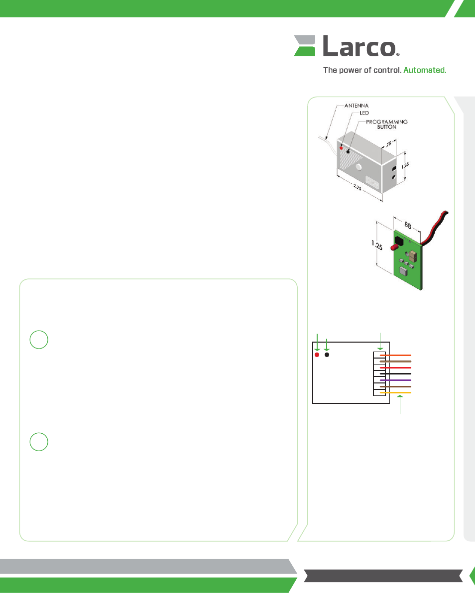
The vestibule sequencer comes equipped with a wiring harness for easy
installation. Reference the wiring diagram (Diagram 2) on the right side of
page for proper connections. The vestibule sequencer must be connected
to the power source before programming, but it is not necessary to connect
the relay output wires at this time. You may want to connect these wires
as your last step as a safety precaution to keep the doors from operating
during the installation. You may remove the power source after the
programming procedure as a safety precaution. The vestibule sequencer is
designed to retain its programming even after power has been removed.
Installation
Follow the installation instructions below for each vestibule sequencer in your
installation. Each door control will require a separate vestibule sequencer unit.
Transmitter –
Item # 234475
Sequencer –
Item # 235215
Diagram 2: Vestibule Sequencer Wiring Harness
Orange: Relay Output – Normally Open
Brown with White Stripe: Relay Output – Common
Red: 24VAC/24VDC Power
Black: Ground
Purple : 12VAC/12VDC Power
Brown: Relay Output – Common
Yellow: Relay Output – Normally Closed
Diagram 1: Vestibule Sequencer and Transmitter
Dimensions
Output N.O.
Output Common
24VAC/24VDC
GND
12VAC/12VDC Power
Output Common
Output N.C.
Orange
Brown/White Stripe
Red
Black
Purple
Brown
Yellow
Approx.
6 in. / 152 mm
Sequencer Terminals
LED
SEQUENCER
Button