Installation and mounting instructions – Larco U-WAV User Manual
Page 2
ATEK Access Technologies
10025 Valley View Road, Ste. 190
Eden Prairie, MN 55344 U.S.A.
PH: 1.800.523.6996
FAX: 1.800.589.3705
+1.218.829.9797
www.atekaccess.com
223-0114-000 Rev. D 2/15
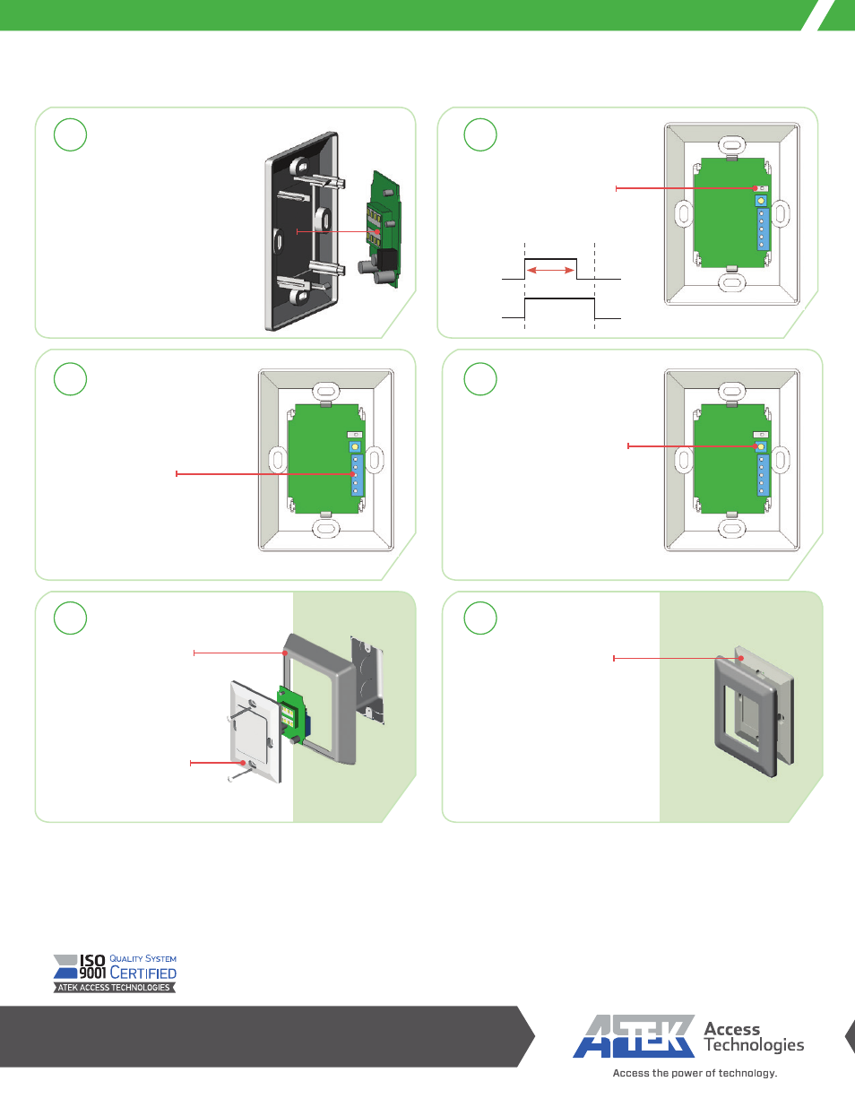
Snap sensor board assembly
onto mounting plate with
microwave sensor facing
mounting plate.
Choose desired mode
of operation, toggle (T)
or pulse (P) with selector
switch.
If using surface mount bevel,
run wiring through bevel
before making connections
to terminal block.
Adjust distance sensitivity
before attaching assembly
to mounting surface. Turn
clockwise for more sensitivity
and greater sensing distance.
Snap cover in position to
conceal mounting screws.
After initializing power to unit,
blue LED lights are ON when idle
and OFF during activation.
Installation and Mounting Instructions
FCC ID: USX-IPM165F
This devise complies with part 15 of the FCC rules. Operation is subject to the following two conditions. (1) This device may not cause harmful interference, and (2) this device must accept any
interference received, including interference that may cause undesired operation. Note: This equipment has been tested and found to comply with the limits for a Class B device, pursuant to part
15 of the FCC rules. These limits are designed to provide reasonable protection against harmful interference in a residential installation. This equipment generates, uses, and can radiate radio
frequency energy and, if not installed and used in accordance with the instructions, may cause harmful interference to radio communications. However, there is no guarantee that interference
will not occur in a particular installation. If this equipment does cause harmful interference to radio or television reception, which can be determined by turning the equipment off and on, the user
is encouraged to correct the interference by one or more of the following measures. Reorient or relocate the receiving antenna. Connect the equipment into an outlet on a circuit different from
that to which the receiver is connected. Increase the separation between the equipment and receiver. Consult the dealer or experienced radio/ TV technician for help.
The user is cautioned that changes and modifications made to the equipment without approval of the manufacturer could void the users authority
to operate this equipment.
Surface mount bevel
is optional.
Attach assembly to
mounting surface with
screws supplied.
P: Relay
T: Relay
1.2 sec
Detect
Detect
1
2
3
4
5
6