Wall switch installation instructions, 3” x 3” box mounting, Cleaning wall switches – Larco Wall Switch User Manual
Page 2: Mounting options
ATEK Access Technologies
10025 Valley View Road, Ste. 190
Eden Prairie, MN 55344 U.S.A.
PH: 1.800.523.6996
FAX: 1.800.589.3705
+1.218.829.9797
www.atekaccess.com
223-0115-000 Rev. E 2/15
2
3
4
5
7
1
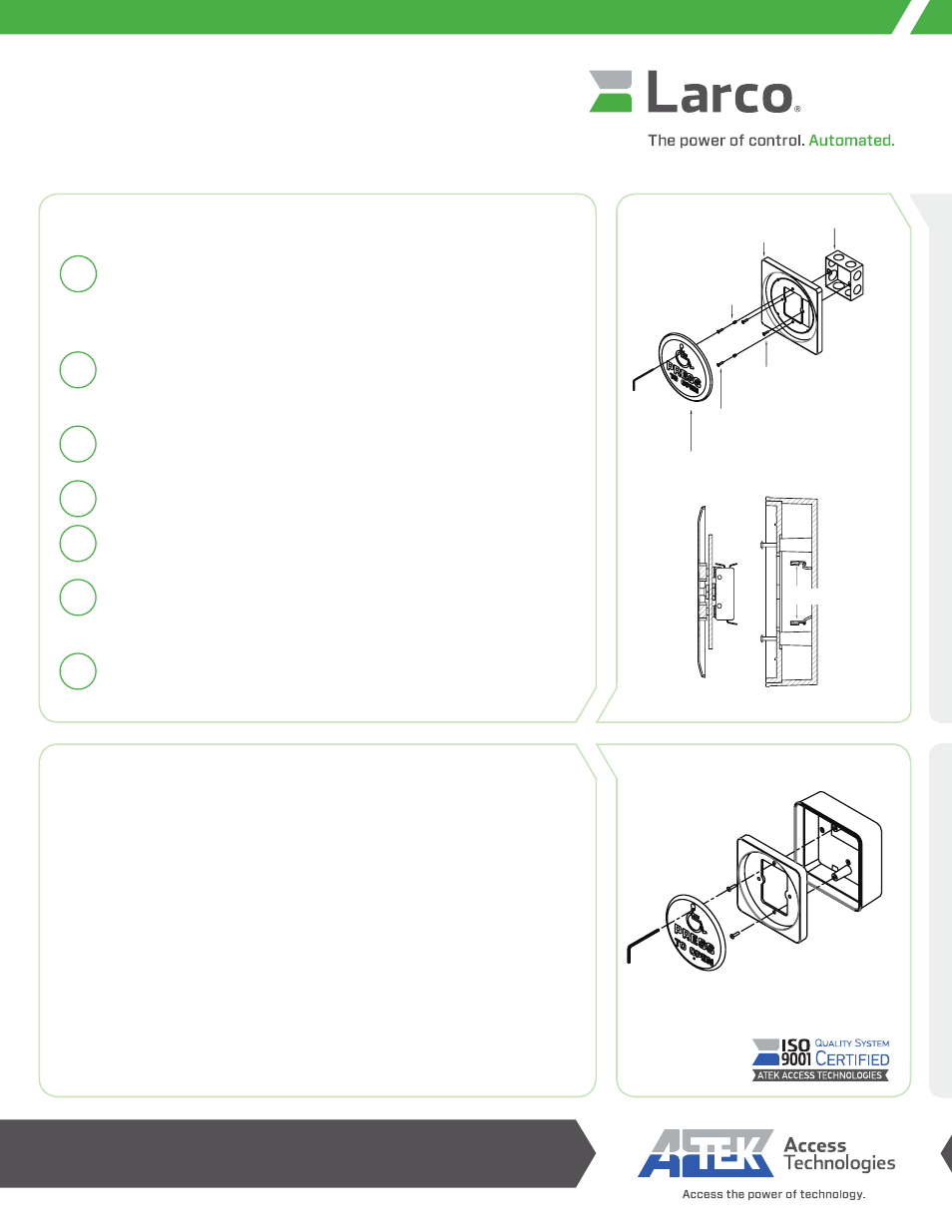
Install a 3” x 3” mounting box in the area in which the wall switch is to be
installed. Bend upper and lower tabs inward to accommodate wall switch.
Be sure there is adequate clearance on each side to accommodate the
adapter plate.
Press the #6-32 screw inserts into the holes in the adapter plate as
shown with the hex head flush to the face of the adapter plate on the side
facing the wall switch.
Thread the enclosed #6-32 screws into the adapter plate, tightening until
approximately 1/4” of the threads remain visible.
Thread the 3” x 3” mounting box screws into the 3” x 3” box and tighten.
Wire the wall switch to the door controller using spade terminals to connect
to the N.O. and COMMON contacts (see drawing to the right).
Slide the back plate of the switch over the #6-32 wall switch screws
and allow it to settle. Use enclosed wrench to tighten and secure wall
switch plate.
Test for activation.
3” x 3” Box Mounting
6
Cleaning Wall Switches
Wall switch cover plates are manufactured from high quality stainless steel and
painted with scuff-resistant coatings. To clean the cover plates, use a damp non-
abrasive cloth. Regular cleaning with harsh solvents or abrasive materials may
cause deterioration of the painted engraving.
Mounting Options
In addition to the mounting options on this sheet, Larco wall switches can be
mounted in any of our specially designed wall switch mounting boxes, like the
universal box shown at right. Use the guidelines included with each box for proper
installation.
Observe all manufacturers’ recommendations for safety and operation of their products. ANSI/BHMA
standards that offer specific recommendations for each type and class of automatic door have been
developed. To obtain a copy of the ANSI/BHMA installation standar
or www.ansi.org.
Wall Switch Installation
Instructions
Wall Switch Wire Connection Drawing
#6-32 WALL SWITCH
MOUNTING SCREWS
WALL SWITCH
#6-32 JUNCTION BOX
MOUNTING SCREWS
3" X 3" BRITISH
JUNCTION BOX
ADAPTER PLATE
#6-32 THREADED INSERT
COM
NO
NC
SPADE
TERMINALS