Microstrip details, Helpful application notes from linx – Linx Technologies TRM-xxx-DP1203 User Manual
Page 10
– –
– –
14
15
Helpful Application Notes from Linx
It is not the intention of this manual to address in depth many of the issues
that should be considered to ensure that the modules function correctly
and deliver the maximum possible performance. We recommend reading
the application notes listed in Figure 20 which address in depth key areas
of RF design and application of Linx products. These applications notes are
available online at www.linxtechnologies.com or by contacting Linx.
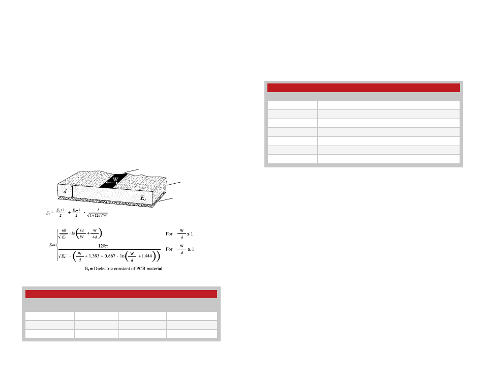
Microstrip Details
A transmission line is a medium whereby RF energy is transferred from
one place to another with minimal loss. This is a critical factor, especially
in high-frequency products like Linx RF modules, because the trace
leading to the module’s antenna can effectively contribute to the length
of the antenna, changing its resonant bandwidth. In order to minimize
loss and detuning, some form of transmission line between the antenna
and the module should be used unless the antenna can be placed very
close (<1/8in) to the module. One common form of transmission line is a
coax cable and another is the microstrip. This term refers to a PCB trace
running over a ground plane that is designed to serve as a transmission line
between the module and the antenna. The width is based on the desired
characteristic impedance of the line, the thickness of the PCB and the
dielectric constant of the board material. For standard 0.062in thick FR-4
board material, the trace width would be 111 mils. The correct trace width
can be calculated for other widths and materials using the information in
Figure 18 and examples are provided in Figure 19. Software for calculating
microstrip lines is also available on the Linx website.
Trace
Board
Ground plane
Figure 18: Microstrip Formulas
Example Microstrip Calculations
Dielectric Constant
Width / Height
Ratio (W / d)
Effective Dielectric
Constant
Characteristic
Impedance (Ω)
4.80
1.8
3.59
50.0
4.00
2.0
3.07
51.0
2.55
3.0
2.12
48.8
Figure 19: Example Microstrip Calculations
Helpful Application Note Titles
Note Number
Note Title
AN-00100
RF 101: Information for the RF Challenged
AN-00126
Considerations for Operation Within the 902–928MHz Band
AN-00130
Modulation Techniques for Low-Cost RF Data Links
AN-00140
The FCC Road: Part 15 from Concept to Approval
AN-00500
Antennas: Design, Application, Performance
AN-00501
Understanding Antenna Specifications and Operation
RG-00103
TT Series Transceiver Command Data Interface Reference Guide
Figure 20: Helpful Application Note Titles