Es series receiver development boarad, Using the development boards, Troubleshooting – Linx Technologies MDEV-xxx-ES User Manual
Page 5
–
–
–
–
4
5
Using the Development Boards
All of the module’s connections are made available to the designer via the
wire-wrap header (TS1 / TS2). Jumper shunts have been provided. These
shunts are placed across adjacent pins to control the routing of TX and RX
data. After unpacking the development system, attach an antenna to each
board, install the supplied 9V battery, and turn on the power switches. The
development board is now ready for use.
Troubleshooting
If the boards fail to work out of the box, then try the following:
• Check the battery to make sure it is not dead.
• Make sure that the antenna is connected.
• Make sure that the jumpers are set correctly.
• Ensure that the baud rate selector switches are set the same on both
boards.
• Create and learn a new address.
If all of these appear to be in order, then you can call 800-736-6677 or
e-mail [email protected].
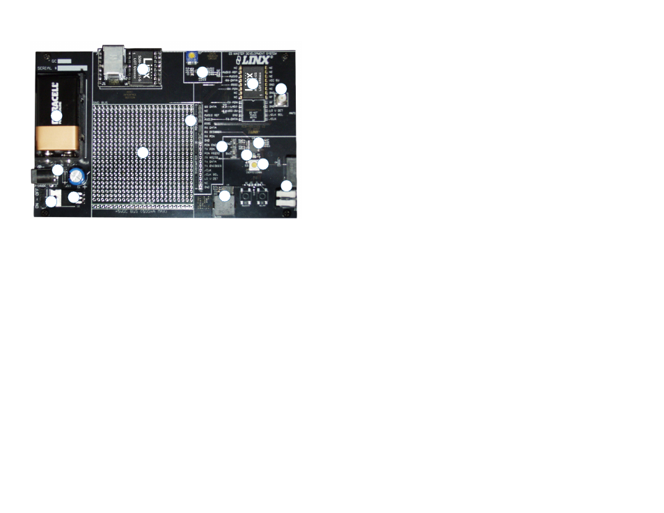
ES Series Receiver Development Boarad
1. 9V Battery
2. DC Power Jack
3. On-Off Switch
4. Voltage Regulator
5. Host Interface Module
6. Prototype Area
7. Data Squelch Circuit
8. Break-Out Header
9. ES Series Receiver
10. RP-SMA Antenna Connector
11. MS Series Decoder
12. Baud Rate Selector Switches
13. MODE_IND LED
14. LEARN Button
15. Buzzer
16. Relay Output
Figure 4: ES Series Receiver Development Board
1
2
3
4
5
6
7
8
9
15
10
11
12
13
14
16