Receivers, Typical applications – Linx Technologies CMD-HHCP-xxx User Manual
Page 7
– –
– –
8
9
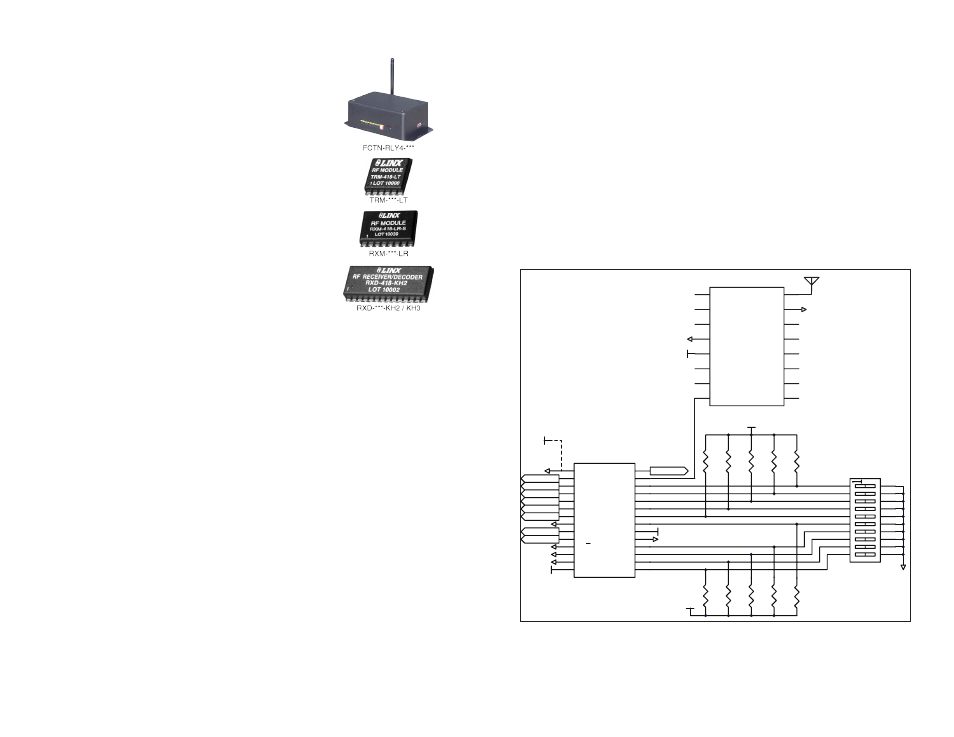
Typical Applications
The outstanding sensitivity of the LR Series receiver offers the best range
when used with the Handheld transmitter. When using the LR Series
receiver, the DS Series decoder chip should be used to decode the
received signal. This decoder has ten address lines that must match the
transmitter address lines. A DIP switch is commonly used to set these,
but they can also be hardwired. As long as the address lines match, when
a button on the transmitter is pressed, a corresponding data line on the
decoder (D0–D7) goes high. These data lines can then be connected
to external circuitry to perform whatever function is required by the
application.
Figure 11 shows a typical schematic using the LR Series receiver and the
DS Series decoder.
P_SEL
1
D0
2
D1
3
D2
4
D3
5
D4
6
D5
7
GND
8
D6
9
D7
10
E/D_SEL
11
D_CFG
12
A_CFG0
13
A_CFG1
14
A0
15
A1
16
A2
17
A3
18
GND
19
VCC
20
A4
21
A5
22
A6
23
A7
24
A8
25
A9
26
TE/DI
27
VT/DO
28
LICAL-EDC-DS001
VCC
GND
GND
GND
VCC
GND
D0
D1
D2
D3
D4
D5
D6
D7
VT
1
2
3
20
19
18
4
5
6
17
16
15
7
8
9
14
13
12
10
11
100k
100k
100k
100k
100k
100k
100k
100k
100k
100k
VCC
GND
VCC
GND
VCC
Holtek
Serial
GND
GND
GND
ANTENNA
NC
1
NC
2
NC
3
GND
4
VCC
5
PDN
6
RSSI
7
DATA
8
NC
9
NC
10
NC
11
NC
12
NC
13
NC
14
GND
15
ANT
16
RXM-xxx-LR
VCC
Figure 11: LR Receiver and DS Decoder Schematic
Receivers
There are four options for receivers within the Linx
product line. The first option is to use one of the OEM
Function Modules, such as the Relay Module. These
items are also pre-certified and can be immediately
included in a product.
The other options are to use one of the Linx receiver
modules. The signal sent by the Keyfob transmitter
can be received by the LR Series receiver module or
the LT Series transceiver module. These modules can
be connected to the DS Series decoder to decode the
signal, or a custom microcontroller can be programmed
to decode it and take specific action.
The KH2 or KH3 Series offers a slightly simpler solution
by combining the LR Series receiver and the Holtek
or DS Series decoder in a single package. The KH2
Series receiver only supports the Holtek protocol, not the
serial protocol. The KH3 Series receiver supports both protocols.
When a button is pressed on the transmitter, a corresponding line on the
decoder goes high (as long as the addresses match). This can then be
connected to whatever circuitry is required by the application.
Application Note AN-00300 discusses in detail how to set the addresses
on all of the units. Data guides for all of the receivers, the Holtek HT640
encoder, HT658 decoder and the DS Series decoder can be found on the
Linx website, www.linxtechnologies.com.
Figure 10: Linx Receivers