Relays, Poor optimum acceptable – Linx Technologies FCTN-RLY4-xxx-2 User Manual
Page 3
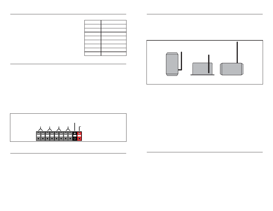
ANTENNA ORIENTATION
Since the control signals for the Relay Function Module are sent through the air,
the physical orientation of the transmitter and receiver plays a critical role in
determining the overall range of the system. The antenna may be tilted and
swiveled to adjust for maximum range in your environment. In most cases,
orienting the antenna in a vertical position will result in optimum system
performance and the greatest range.
The placement of the module in the final product will also affect the range and
performance of the system. If the module is to be placed inside an enclosure,
then the enclosure must be plastic or another non-conductive material.
Otherwise, a hole must be cut into the enclosure to allow the antenna to stick out
as the metal or conductive enclosure will shield the module and it will not be able
to receive a valid transmission. In this case, the antenna should stick straight out
of the enclosure and should not be bent to rest parallel to the metal. This will
detune the antenna and significantly reduce its performance.
The module should be placed in a position to have the widest line-of-sight field
so that the range may be maximized. Typically, the module will be placed on top
of the product to accommodate this, especially when used with machinery.
Remote location of the module’s antenna is not possible as it will invalidate the
FCC testing, so the positioning of the module and its antenna is an important
consideration in the design of the system.
CONTENTION CONSIDERATIONS
An unlimited number of Relay Function Modules may be operated in proximity
without interference, but only one transmitter at a time can be activated within a
reception area. While the transmitted signal consists of encoded digital data,
only one carrier of any particular frequency can occupy airspace without
contention at any given time. If two transmitters are activated in the same area
at the same time, the signals will interfere with each other, so the Relay Module
will not see a valid transmission and will not take any action.
Page 5
Page 4
RELAY LATCHING
The relays can be set to either latching or momentary operation. When latched,
the relays close when an activation command is
received and stay closed until a deactivation
command is received. When momentary, the
relays close for as long as an activation
command is received. When the activation
command ceases, the relays open. The four-
position DIP switch, S2, sets the individual
relays to either latching or momentary
operation. The table to the right identifies the
data line activations that affect relay operation.
SWITCHED DEVICE ATTACHMENT
The Relay Function Module features heavy-duty quick-connect block terminals
for attaching the devices to be switched. To use the terminals, press and hold
the button over the entry channel to release the contact. Insert the wire and then
release the button to allow the internal contact to clamp down on the wire.
The terminals accept wire gages from 16 to 26 AWG. Funnel-shaped entry
channels help prevent fraying when using untinned wire. The terminal block is
arranged as shown in the figure below. There is no polarity on the relay terminals
and they may be used in any order (or left unterminated) without internal
damage. Do not attempt to switch loads in excess of the limits listed in the
Electrical Specifications section. The module does not provide internal protection
for shorted loads. Therefore, the designer must provide external protection, such
as fusing, if the possibility of shorting exists.
INTERFERENCE CONSIDERATIONS
It is important to remember that the range performance of the modules is heavily
dependent on the environment in which they are operated. The effects of
interference, multipath, and physical attenuation will vary significantly from
location to location.
The Relay Function Module is based on the Linx LR Series RF receiver. These are
simple low-cost receivers intended for short-range transmissions. They utilize OOK
AM-based modulation. AM devices can be affected by external noise, such as that
from motors or other sources of broadband RF emissions. Interference can also
come from sources such as paging towers or amateur radio activity. The designer
should carefully test the Relay Function Module in the environment in which it will
be used to ensure that its performance is appropriate for the chosen application.
RELAYS
1
2
3
4
GND
7-30VDC
Figure 5: Relay Connection Block
Poor
Optimum
Acceptable
Figure 6: FCTN-RLY4-***-2 Antenna Orientation
Data Line
Relay Operation
D0
Relay 4 ON
D1
Relay 4 OFF
D2
Relay 3 ON
D3
Relay 3 OFF
D4
Relay 2 ON
D5
Relay 2 OFF
D6
Relay 1 ON
D7
Relay 1 OFF