Magnum Energy DC Breakers (BR-DC) User Manual
Page 2
DC Load Breakers (Back Mount Type) Instruction Sheet
2
© 2013 Magnum Energy, Inc.
WARNING: During normal operation, terminals, busbars, and elec-
trical components inside the MMP/MP enclosure may be energized
- DO NOT TOUCH. Disconnect all power sources before removing the
cover. Failure to take action could result in physical harm.
Installation Steps:
Info: The MMP enclosure is shown in Figure 2, however the in-
stallation is similar in MP installations.
1. Remove the breaker front panel cover only after all power has been removed
from the MMP (Mini Magnum Panel) or MP (Magnum Panel) system.
2. Remove the DIN rail track on the breaker mounting plate by removing the
#8-32 x 3/8” (T15 head) Torx screws holding this track.
Info: The holes in the mounting plate — for the Torx screws that
hold the breakers — are NOT threaded. Prior to mounting the
breaker, use a power-driver to pre-thread the holes in the mount-
ing plate with the self-threading Torx screws (T20 head) provided.
3. After the holes in the mounting plate have been pre-threaded, place the
back mount breaker(s) against the mounting plate and loosely secure them
using the two #8-32 x 1/2” (T20 head) Torx screws provided. Do not fully
tighten these Torx screws, that will be done in Step 5 after being aligned.
4. For each breaker installed, remove only the knockouts in the front panel
cover that are needed for the width of the breaker. Each breaker uses a 1”
opening, which requires removing 2 knockout slots (1 knockout = 1/2” slot).
5. Ensure each breaker aligns correctly into the spaces — made by the
knockouts removed from the front panel cover — by placing the front panel
cover over the DC breakers. If the fi t and alignment are correct, use a hand
driver to tighten the Torx screws to secure each DC breaker.
CAUTION: The slotted mounting brackets on the breaker are made
of plastic. DO NOT OVERTIGHTEN the Torx screws used to hold the
breaker to the mounting plate or the brackets may break. It is highly
recommended to use a hand driver to tighten the screws.
The DC breaker is now installed and ready to be wired to the DC circuit.
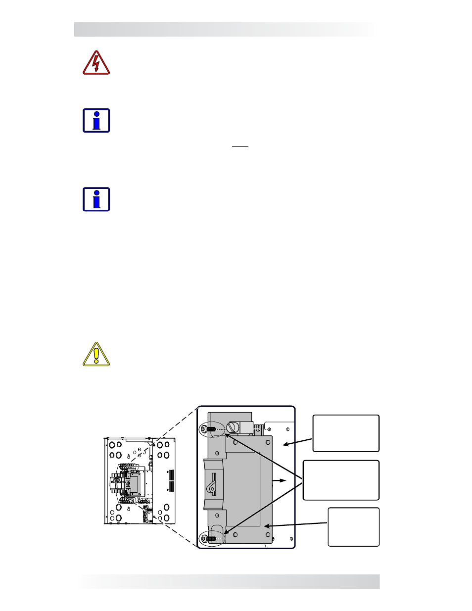
Figure 2, Installing Back Mounted DC Breakers
Two DC breaker
mounting screws
( #8-32, use 1/2”
length minimum)
Back
mounted
DC breaker
(1” width)
Remove DIN
rail and screw
breaker to
mounting plate.