Initial use – Parkside PHKSA 18-Li A1 User Manual
Page 11
8
PHKSA 18-Li A1
GB
Removing the battery pack:
♦
Press the release button and remove the
battery pack .
Checking the battery charge level
♦
Press the battery charge level button to
check the status of the battery (see also main
diagram). The status/remaining charge will be
shown on the battery display LED as follows:
♦
RED/ORANGE/GREEN = maximum charge/
power
RED/ORANGE = medium charge/power
RED = low charge – charge the battery
Checking the blade guard
♦
Pull back on the release lever for the blade
guard as far as the stop.
The blade guard must move freely without jam-
ming and must spring back into its starting position
automatically when you let go of the release lever
for the blade guard .
Initial use
Fitting/changing the saw blade
Always remove the battery pack before changing
the saw blade !
1. Set the cutting depth (using the locking screw )
to the minimum position, 0 mm.
2. Swing the blade guard back using the
release lever and put the appliance down.
3. Press the spindle lock button (until it engages)
and use the Allen key to release the clamping
screw . Now remove the clamping screw
and the clamping fl ange (see also Fig. A).
Fig. A Changing the saw blade
4. Remove saw blade.
5. Fitting a saw blade is carried out in the reverse
order.
6. Press the spindle lock button (until it engages)
and use the Allen key to tighten the clamping
screw .
WARNING!
►
The arrow on the saw blade must corre-
spond to the arrow showing the direction
of rotation (running direction shown on the
appliance).
■
Ensure that the saw blade is suitable for the
rotational speed of the tool.
Rip fence
♦
Loose the wing screw and insert the rip
fence into the rip fence slot .
♦
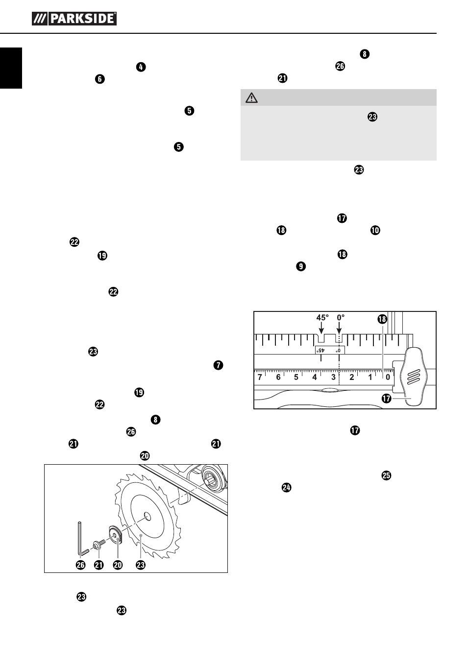
Set the desired cut width with the help of the
scale on the rip fence and the cut out in the
base plate (see also Fig. B).
The right-hand recess in the base plate is for a
cutting angle of 0°. The left-hand recess in the
base plate is for a cutting angle of 45°.
Fig. B: Cutting width 3 cm
♦
Retighten the wing screw .
Connecting the sawdust extraction
device
♦
Attach the dust extraction adapter to the chip
ejector .
Optional depending on the diameter of the dust
and sawdust extractor.
♦
Connect an approved dust and chip extraction
device.
IB_102867_PHKSA18-LiA1_LB4.indb 8
13.10.14 11:07