Kichler 9510 User Manual
Kichler Lighting
ALL INSTALLATIONS SHOULD COMPLY WITH LOCAL ELECTRICAL
CODES FOR FIXTURE MOUNTING AND WIRING METHODS. IF YOU
HAVE ANY DOUBTS CONCERNING INSTALLATION CONTACT A QUAL-
IFIED ELECTRICIAN.
FIXTURE IS PROVIDED WITH THE NECESSARY HARDWARE FOR
INSTALLATION IN ACCORDANCE WITH A NEWLY POURED CON-
CRETE PAD. CONCRETE PAD MUST BE AT LEAST 13" SQUARE AND
18" DEEP.
1)
On threaded end of J-bolts make a mark 2" from end.
2)
Prepare area for concrete pad and poor concrete following manufacturers
recommendations.
3)
Pass J-bolt through hole in template until mark made in step 2 is at bottom
edge of template.
4)
Embed J-bolts in concrete pad until template sits on top of concrete pad.
Care should be taken to insure J-bolts stay straight. Using post base
make sure alignment of J-bolts is maintained being
careful not to move bolts or come in contact with wet concrete.
5)
Allow time for concrete to cure (reference manufacturers
recommendations).
6) Remove
template.
7)
Place post base on top of concrete pad allowing J-bolts to pass
through holes.
8)
Secure post base in place using washers and hexnuts.
9)
Align holes in bottom of post top with threaded holes in top of
post base.
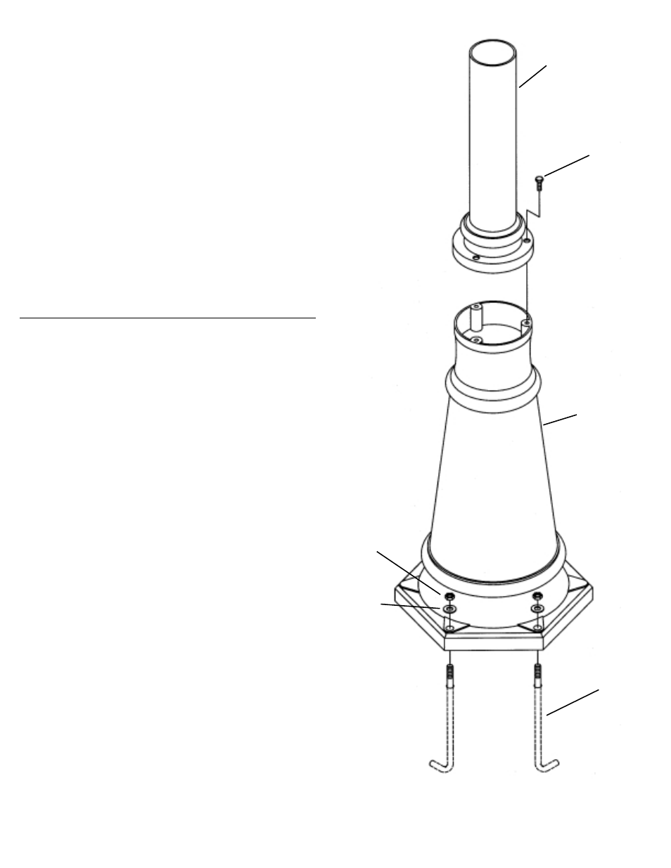
10) Secure post top and post base together using bolts.
TODAS LAS INSTALACIONES DEBEN CUMPLIR CON LOS CÓDIGOS
ELÉCTRICOS LOCALES PARA EL MONTAJE DE ARTEFACTOS Y
MÉTODOS DE CABLEADO. SI USTED TUVIERA ALGUNA DUDA RELA-
CIONADA CON LA INSTALACIÓN, COMUNÍQUESE CON UN ELEC-
TRICISTA CALIFICADO.
EL ARTEFACTO SE SUMINISTRA CON EL HERRAJE NECESARIO
PARA LA INSTALACIÓN EN UNA ZAPATA DE CONCRETO RECIÉN
VACIADA. LA ZAPATA DE CONCRETO DEBE SER, COMO MÍNIMO UN
CUADRADO DE 13" Y DE 18" DE PROFUNDIDAD.
1)
En el extremo roscado de los pernos J haga una marca de 2" desde el
extremo.
2)
Prepare el área para la zapata de concreto y vacíe el concreto siguiendo
las recomendaciones del fabricante.
3)
Pase el perno J a través el agujeros en la plantilla hasta que la marca
hecha en el paso 2 esté en la parte inferior de la plantilla.
4)
Embeba el perno J en la zapata de concreto hasta que la plantilla sienta
en el tope de la zapata de concreto. Se debe tener cuidado para asegurar
de que los pernos J se mantengan derechos. Utilizando la base del
poste, asegúrese de que la alineación de los pernos J se mantenga,
teniendo cuidado de no mover los pernos o de que entren en contacto
con el concreto fresco.
5)
Deje pasar el tiempo necesario para que fragüe el concreto (consulte
las recomendaciones del fabricante).
6)
Quite la plantilla.
7)
Ponga la base del poste sobre la parte superior de la zapata de concreto
haciendo que los pernos J pasen a través de los agujeros.
8)
Asegure la base del poste en el lugar utilizando las arandelas y tuercas
hexagonales.
9)
Alinee los agujeros en la parte inferior del tope del poste con los agujeros
roscados en el tope de la base del poste.
10) Asegure juntos el tope del poste y la base del poste utilizando los pernos.
POST TOP
TOPE DEL POSTE
BOLT
PERNO
POST BASE
BASE DEL POSTE
HEXNUT
TUERCA
HEXAGONAL
WASHER
ARANDELA
J-BOLT
PERNO J
Date Issued: 11/30/01
IS-9510-US