Kichler 16030 User Manual
Kichler Lighting
SAFETY INSTRUCTIONS
READ THIS FIRST
KEEP THESE INSTRUCTIONS
This fixture is intended for installation in accordance with the National
Electric Code (NEC) and Local code specifications. Failure to adhere to
these codes and instructions may result in serious injury and/or property
damage and will void the warranty.
WARNING – RISK OF ELECTRIC SHOCK
• Do not mount luminaire within 10 feet (3m) of a swimming pool, spa or
fountain.
• This fixture is to be used only with a Kichler
®
low voltage lighting power
unit (transformer) rated a maximum 15 volts, 300 W per secondary (25 AMPS)
NOTE: If additional Direct Burial wire is needed, contact your local Kichler
®
landscape distributor.
• 8 GA wire can be purchased in length of 250’ (76 M), 15503-BK.
• 10 GA wire can be purchased in length of 250’ (76 M), 15504-BK.
• 12 GA wire can be purchased in lengths of 100’ (30 M), 15501-BK; 250’
(76 M), 15502-BK; 500’ (152M), 15505-BK; and 1000’ (304 M), 15506-BK.
Date Issued: 1/13/12
IS-16030-US
For warranty information please visit: http://www.landscapelighting.com/portal/warranty_page
Para informacion de la garantia por favor visite: www.landscapelighting.com/portal/warranty_page
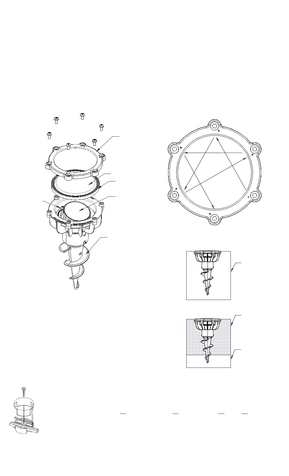
SPHERE
RETAINING
SCREWS
TORNILLOS DE
RETENCIÓN DE
LA ESFERA
GLASS
SEALING RING
ANILLO
OBTURADOR
DE VIDRIO
GLASS
VIDRIO
GASKET
JUNTA
SPHERE
ESFERA
THREADED STAKE
ESTACA ROSCADA
FIXTURE ASSEMBLY AND INSTALLATION
1. Turn off power.
2. Determined desired location of fixture and dig hole. Hole should be 9"
(diameter) x 6" (deep) if working in soft soil, such as sand. If working in
hard or compacted soil, such as clay, dig a 9" (diameter) x 10" (deep) hole.
3. If installing in soft soil: Use the threaded stake to dig into the ground
and temporarily stabilize the fixture.
If installing in hard soil: Fill the bottom of the hole with approximately 3"
(76mm) of pea gravel. Place the fixture in hole and back fill around the
fixture with soil, up to the wire exit hole.
4. Make wire connections using supplied Quic Disc™ following the instructions
below, or using other approved wiring connection method (not supplied.)
The fixture wire is not intended for direct burial. According to the requirements
of the National Electric Code (NEC), direct burial rated wire is to be buried
a minimum of 6" [152mm] beneath the surface of the ground.
5. To aim the beam: Remove the glass sealant ring by removing the six (6)
screws on top of the fixture. Loosen the screws on the sphere retaining
ring until the sphere becomes unfixed. Aim the beam as desired. (up to
15°) Re-tighten the screws on the sphere retaining ring until the sphere is
secure and does not rotate. Clean sealing surface, and replace glass,
gasket, and glass sealing ring. Install and torque screws in triangular
pattern, following the numbers screws holes 1-6.
6. Back fill around the fixture with soil.
SOIL
SUELO
FOR INSTALLATION IN SOFT SOILPARA
INSTALACIÓN EN SUELOS BLANDOS
SOIL
SUELO
FOR INSTALLATION IN HARD SOIL
PARA INSTALACIÓN EN SUELOS DUROS
3" (76 MM)
OF PEA GRAVEL
3” (76 MM) DE
GRAVA DE RÍO
START
INICIO
TIGHTEN SCREWS IN TRIANGULAR PATTERN SHOWN ABOVE.
AJUSTE LOS TORNILLOS EN FORMA TRIANGULAR TAL COMO SE
MUESTRA ANTERIORMENTE.
QUIC DISC
™
WIRING INSTRUCTIONS
Turn off power.
The full length of the 18 GA fixture wire may be used to connect with the 10 GA or 12 GA cable provided the following conditions are met:
• Wiring is to be protected by routing close to the fixture or accessory or secured to a building structure such as house or deck.
• 18 GA fixture wiring is to be cut off so that it is attached to the connector within 6 inches of the fixture or building structure.
• If it is necessary to make the connections underground, then no more than 6 inches of the 18 GA fixture wire is to be buried.
The Quic Disc
™
connector is designed to install one fixture and accommodates one 18 GA fixture wire and one 10 GA or one 12 GA supply wire.
Place the 10 gauge supply wire across the area marked 10 GA on Quic Disc
™
or place the 12 gauge supply wire across the area marked 12 GA
on Quic Disc
™
.
Place the 18 gauge fixture wire across the area marked 18 GA on the Quic Disc
™
. After the wires are in place, connecta the top of the Quic
Disc
™
to the base with supplied screw, making sure that the wires remain flat in the bottom portion of the Quic Disc
™
, and the screw is tightened
all the way down.
The copper contacts will automatically pierce the wires’ insulation. Excess 18 GA fixture wire that sticks out the end of the Quic Disc
™
is to be cut off.
Make no other wiring connections to the 18 GA fixture wire.