Fig.3 fig.5 fig.4 fig.6 – Sealey WS570 User Manual
Page 2
4. MAINTENANCE
5. SPARE PARTS
Declaration of Conformity
We, the sole importer into the UK, declare that the product listed below is in conformity with the following EEC standards and directives
The construction file for this product is held by the Manufacturer and may be inspectedby a national
authority upon request to Jack Sealey Ltd.
For Jack Sealey Ltd. Sole importer into the UK of Sealey Quality Machinery.
WHEEL SKATES
Model: WS570
93/68/EEC CE Marking Directive
98/37/EEC Machinery Directive (S.I.1992/3073 & Amendments)
17th May 2001
01284 757500
01284 703534
Sole U.K. Distributor
Sealey Group,
Bury St. Edmunds, Suffolk.
WS570 - 3 - 230702
Signed by Mark Sweetman
3.3.
Positioning the Skate.
3.3.1. Take hold of each side of the frame and expand the unit until it is wide enough to slide
the rollers either side of the tyre. (See fig.1) Make sure that both sets of rollers are centred
on the tyre then push the unit together again until each pair of rollers are in contact with
the tyre.
3.4.
Raising a wheel.
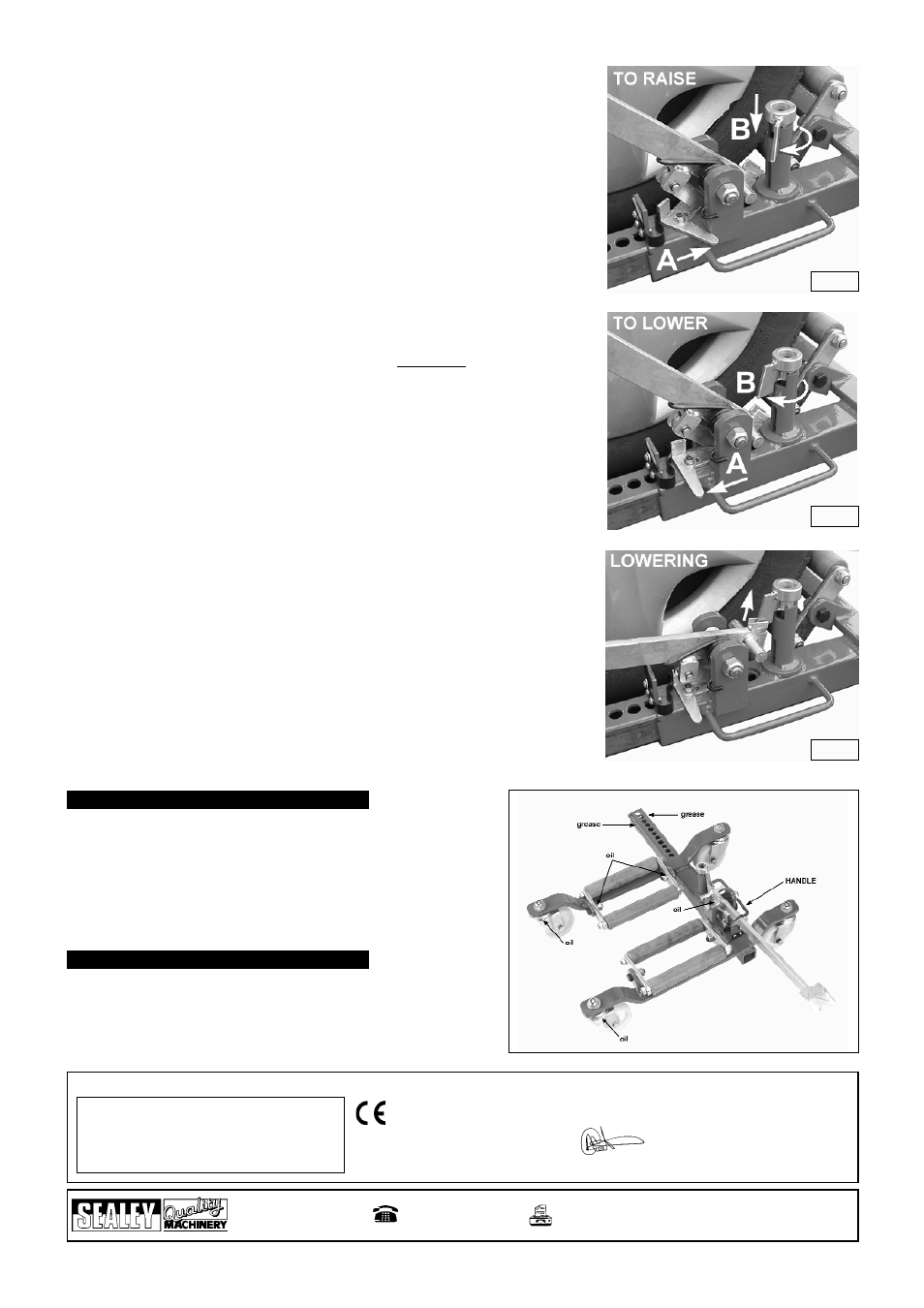
3.4.1. Now engage the ratchet by turning the ratchet lever as far as it will go to the right. See
fig.3 - A.(TO RAISE)
3.4.2. Engage the locking pin by turning the tab clockwise until it drops into the slot. Once in the
slot the tab should be turned away from the pedal lever. See fig.3 - B.(TO RAISE)
3.4.3. Operate the foot pedal lever to commence raising the wheel. ( IMPORTANT - Allow the
pedal to return through its full travel before commencing the next stroke.)
Continue until the tyre is 2cm clear of the ground.
3.4.4. Raise the second wheel off the ground with the other Skate. Be prepared for any movement
the vehicle may make when the second wheel comes clear of the ground. This is
particularly important when using four skates. Providing the ground/floor is level the vehicle
should remain stable. ( Read safety precautions in Section 1.)
3.5.
Moving the Vehicle.
3.5.1. Ensure that you have sufficient manpower to move and control the vehicle. Keep well
away from any sloping areas or entry ramps to the area however shallow they may appear.
When positioning a vehicle in relation to a wall or feature such as a pillar no persons or
objects should be situated between the vehicle and the feature. Sufficient space should
be left between the side of a vehicle and an adjacent wall or feature to allow the Skates
to be withdrawn sideways.
3.6.
Lowering wheels.
3.6.1. Disengage the ratchet by turning the the ratchet lever to the left. See fig.4 - A(TO LOWER)
3.6.2. Turn the locking pin tab clockwise in its slot so that it is in line with the small U shaped
channel at the bottom of the foot pedal lever. See fig.4 - B. (TO LOWER)
3.6.3. Operate the foot pedal lever through its full travel to commence lowering in controlled
stages.The last movement of the lever will raise the locking pin (see fig.5 LOWERING)
to allow the unit to open whilst the ratchet lever acts as a stop to lock the unit in the next
hole down. Continue to operate the lever through its full travel until the tyre is on the ground
and no longer exerting pressure on the rollers.
3.7.
Removing the Skate.
3.7.1. Lift the locking pin and tab and turn it anticlockwise until the tab is no longer engaged in
the slot. The unit is now free to open.
3.7.2. Expand the unit sufficiently to clear the tyre and move it away from the wheel.
3.8.
To carry the unit.
3.8.1. With the locking pin and ratchet disengaged push the unit together as far as it will go.
Push the foot pedal down and engage the transit hook. For balanced carrying use the wire
rod handle welded on the side of the square tube. (See Fig.6.)
fig.3
fig.5
fig.4
fig.6
4.1. Periodically lubricate the wheels, roller pivots and the foot pedal lever
pivot with oil as shown in fig.6. Lightly grease the four faces of the
square section tube as shown in fig.6 then open out the unit to its full
extent and grease the faces of the tube previously hidden.
5.1. Please see separate parts list and diagram.
E-mail: [email protected]
Web: www.sealey.co.uk