Sealey MK65 User Manual
Masking paper dispenser 1 x 450mm roll, Mk65.v2, Fig.1 fig.2
Original Language Version
INSTRUCTIONS FOR:
MASKING PAPER DISPENSER
1 x 450mm ROLL
MODEL NO:
MK65.V2
Thank you for purchasing a Sealey Product. Manufactured to a high standard this product will, if used according to these instructions and properly
maintained, give you years of trouble free performance.
IMPORTANT: PLEASE READ THESE INSTRUCTIONS CAREFULLY. NOTE THE SAFE OPERATIONAL REQUIREMENTS, WARNINGS AND CAUTIONS.
USE THIS PRODUCT CORRECTLY AND WITH CARE FOR THE PURPOSE FOR WHICH IT IS INTENDED. FAILURE TO DO SO MAY CAUSE DAMAGE
OR PERSONAL INJURY AND WILL INVALIDATE THE WARRANTY. PLEASE KEEP INSTRUCTIONS SAFE FOR FUTURE USE.
Ensure the dispenser is on a reasonably flat, level floor or wall mounted securely before loading.
Ensure that all fittings are tight and secure.
Be aware that the paper cutting blades are sharp, handle with care.
DO NOT use the dispenser for any purpose other than that for which it is designed.
DO NOT sit or stand on the dispenser.
1. SAFETY INSTRUCTIONS
2. ASSEMBLY
MK65.V2 Issue: 1 05/04/13
2.1. Contents
2.1.1. Check the contents against the list below and if any items are missing or damaged contact your supplier immediately.
● Paper Cutter ● Paper Spring
● Base x 2
● Hand Screw ● Frame Side x 2
● Top Handle
● Cross Tube ● Paper Bar ● Tape Reel x 2 ● Knob
● Bag of fittings
Fittings:
● Foot x 4
●Spring x 2
● Slide Ring x 2 ● Paper Washer x 2 ● Washer, 1/4" x 16
● Nut, 1/4" x 4 ● Wing Nut, 1/4" x 4 ● Screw, 3/16" x 1/2" x 4 ● Screw, 1/4 x 1-1/2"x 4 ● Bolt, 1/4 X 3-1/2" X 2
●Screw, 5/16 x 1-1/2" x 4
● Washer, 5/16" x 4
● Hub x 2
2.2. Assembly
Note: Numbers in brackets refer to item numbers in the Parts List.
2.2.1. If dispenser is to be free standing fit the four feet (16) to the side frames (1).
2.2.2. If the dispenser is to be bench or wall mounted fit the two bases (9) to the rear legs of the side frames (1),
using 5/16” x 1-1/2” screws (15), 1/4” washers (14) and 1/4” nuts (13). Fit two of the feet (16) to the front
legs of the side frames (1).
2.2.3. Attach the top handle (2) to the top of the side frames (1) using 5/16 x 1-1/2” screws (12) and 5/16”
washers (11).
2.2.4. Attach the two side frames (1) to the cross tube (4) using 5/16 x 1-1/2” screws (12) and 5/16” washers (11).
Do not fully tighten screws at this stage.
2.2.5. Attach paper spring (17) loops to either end of the paper cutter (3), as shown in fig.1.
2.2.6. Fit paper cutter (3) to upper holes in front legs of side frames (1) using 1/4 x 1-1/2” screws (15), 1/4” washers
(14) and 1/4” nuts (13).
2.2.7. Tighten all screws/nuts.
2.2.8. Insert 1/4 x 3-1/2” bolts (22) through front legs of side frames (1) and tighten in place using 1/4” washers (14) and 1/4” nuts (13).
2.2.9. Thread a wing nut (18) onto each of bolts (22)
with the wings towards the frame leg.
2.2.10. Slide washer (14) and hub (21) onto each bolt (22) and then fit tape reels (20) onto hubs (21) with open sides towards side frame (1) legs.
2.2.11. Retain tape reels with washer (14) and wing nut (18).
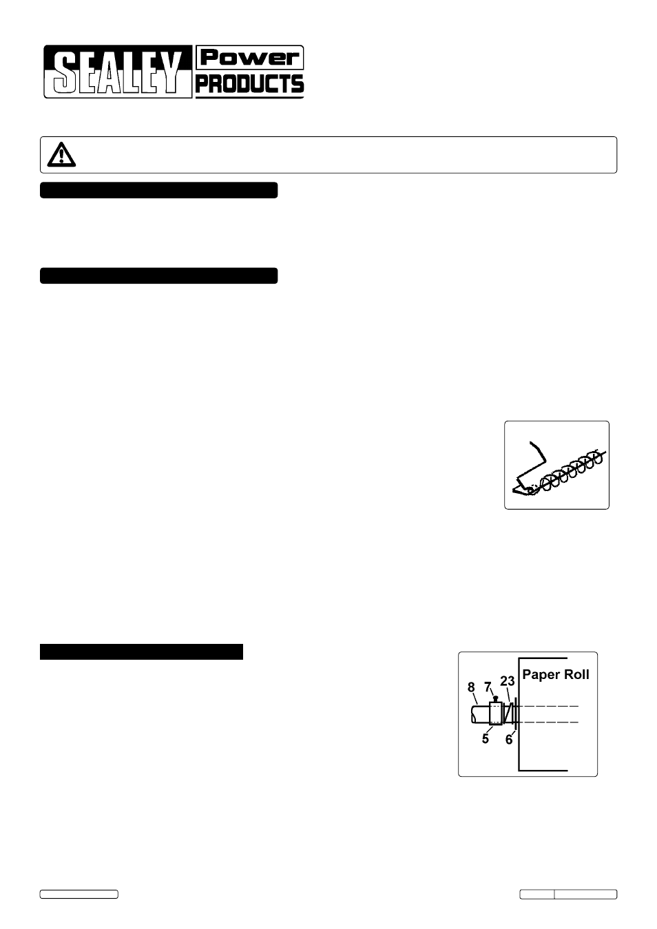
2.2.12. Fit paper washers (6), paper bar spring (23) and paper retainers (5) to paper bar (8) as shown in fig.2. Insert 3/16 x 1/2” screws (7)
into paper retainers (5).
2.2.13. Locate paper bar (8) between bars of side frames (1) and retain with knob (24).
fig.1
fig.2
3. USE
3.1.
Remove paper bar (8) from frame and remove washers (6), springs (23) and retainers (5).
3.2.
Slide paper bar (8) through centre of masking paper roll so that, when reinstalled in frame,
paper will come from top of roll towards front of dispenser.
3.3.
Replace washers (6), springs (23) and retainers (5), as shown in fig.2, at each end of roll.
If two narrow rolls are used fit one spring and paper washer per roll and use the two extra paper
retainers.
3.4.
Refit paper bar, complete with paper roll, to frame assembly. Position roll in centre of bar and
fix in place by tightening screws (7) in paper retainers (5).
3.5.
Thread leading edge of paper between paper spring (17) and guide edge of paper cutter (3),
see fig.1.
3.6.
Press masking tape rolls onto tape reels (20) so that tape leaves bottom of rolls towards the
rear of the dispenser. Rolls may be positioned relative to the masking paper edges by adjusting wing nuts (18).
© Jack Sealey Limited