Sealey SDAST User Manual
Sdast.v2, Fig.2, Fig.1
01284 757500
01284 703534
Sole UK Distributor
Sealey Group,
Bury St. Edmunds, Suffolk.
www.sealey.co.uk
Web
NOTE: It is our policy to continually improve products and as such we reserve the right to alter data, specifications and component parts without prior notice.
IMPORTANT: No liability is accepted for incorrect use of product. WARRANTY: Guarantee is 12 months from purchase date, proof of which will be required for any claim.
INFORMATION: For a copy of our latest catalogue and promotions call us on 01284 757525 and leave your full name and address, including postcode.
Thank you for purchasing a Sealey Product. Manufactured to a high standard this product will, if used according to these instructions and properly maintained, give you years of trouble free performance.
IMPORTANT: PLEASE READ THESE INSTRUCTIONS CAREFULLY. NOTE THE SAFE OPERATIONAL REQUIREMENTS, WARNINGS AND CAUTIONS. USE THIS PRODUCT
CORRECTLY AND WITH CARE FOR THE PURPOSE FOR WHICH IT IS INTENDED. FAILURE TO DO SO MAY CAUSE DAMAGE OR PERSONAL INJURY AND WILL INVALIDATE
THE WARRANTY. PLEASE KEEP INSTRUCTIONS SAFE FOR FUTURE USE.
ASSEMBLY INSTRUCTIONS FOR:
DOUBLE STAND FOR AIR PANEL DRYER
MODEL:
SDAST.V2
WARNING! Ensure Health & Safety, local authority and general
workshop practice regulations are adhered to when using this stand.
Use the stand in a suitable work area.
Keep work area clean, uncluttered and ensure adequate lighting.
DO NOT use the stand
for a purpose for which it was not designed.
DO NOT use stand on uneven ground.
DO NOT use stand if any part is significantly damaged.
Ensure the SDA01 is securely fixed to the stand using the correct
mounting brackets.
Keep children and unauthorised persons away from the work area.
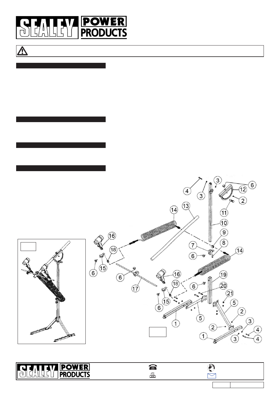
Unpack the product and check the contents against the diagram. (Fig. 2).
Should any items be missing or damaged contact your Sealey dealer.
NOTE: GUNS (ITEM 16) NOT SUppLIED.
Stand will support one or two SDA01 Air panel Dryers allowing operator
more time for other tasks. Fully adjustable for height and dryer angle.
Supplied with air hoses and fittings. (If used with only one dryer the
second outlet must be closed with a suitable 1/4”BSp plug - not supplied).
4.5
Attach the angle disc (12) to the upright (10) using the pivot bolt
(4) two washers (3) and lock nut (2). Screw the sprung locking
pin (11) to the bracket welded onto the upright (10) allowing the
round ended pin to pass into one of the holes in the angle disc.
4.6
Slide the extended tube (13) into the angled disc (12) and
secure with the locking knob (6).
4.7
Slide the lock shaft (17) onto the extended tube (13) and secure
with a locking knob (6).
4.8
Attach the brackets (15), one on either side of the lock shaft
(17) and secure using locking knobs (6).
4.9
Insert the threaded portion at the base of each SDA01 dryer
handle (16) through the hole in each support bracket (15).
Retain each dryer on each bracket by screwing an internally
threaded joint (18) to clamp each dryer head in position.
4.10 Attach a coiled air hose (14) to each dryer head by screwing it
into the other end of the internally threaded connector.
4.11
place the air inlet block (9) onto the adjustable bracket (7).
pass the external thread of the connector (8) through the under
side of the bracket and screw it into the underside of the block.
Tighten the connector until the air inlet block is firmly clamped
onto the bracket.
4.12 Screw the other end of the two air hoses (14) into either side of
the air inlet block (9).
4.13 Tighten all bolts to conclude assembly.
Fig.1
Fig. 2
SDAST.V2
ISSUE NO.1 - 28/03/08
Note: All number references are to Fig.2 below.
4.1 Take the two leg components (5) and loosely bolt the two
upper brackets together using four bolts (20) and four nuts (21).
4.2 Slide the square bottom tube (19) in between the brackets and
further tighten the fixings to clamp the bottom end of the tube
in position. Ensure that the hole for the clamping knob (6) is at
the top of tube.
4.3 Attach the two base feet tubes (1) to the two legs (5) using two
bolts (4) two washers (3) and two nuts (2) on each side.
Ensure that the feet are offset in the same direction.
4.4 Slide the adjustable bracket (7) onto the upright (10)
ensuring that the locking knob will face the front.
Slide the upright assembly (10) into the base tube (19) and lock
it at desired height using lock knob (6).
fig.1
fig.2
1.
SAFETY INSTRUCTIONS
2.
DESCRIPTION
3.
CONTENTS
4.
ASSEMBLY