Fig.1 fig 3, Fig.2, Technical specification – Sealey SM14 User Manual
Page 2: Assembly & adjustment, Operating instructions 5. maintenance
2. TECHNICAL SPECIFICATION
Belt: . . . . . . . . . . . . . . . 915 x 100mm
Belt Speed: . . . . . . . . . . . 460mtr/min
Disc Diameter: . . . . . . . . . . . . 150mm
Disc Speed: . . . . . . . . . . . . . 2950rpm
Table: . . . . . . . . . . . . . . 225 x 160mm
Table Tilt: . . . . . . . . . . . . . . . . . . . .45°
Dust Extraction Port: . . . . . . . . 35mm
Motor:. . . . . . . . . . . . . . . . 500W 230V
Weight:. . . . . . . . . . . . . . . . . . . . .22kg
3. ASSEMBLY & ADJUSTMENT
3.1.
Unpack the sander and check the contents. Should there be any damaged or
missing parts, contact your supplier immediately.
3.2.
Attach a sanding disc (fig.2.1) to the back plate by removing the self adhesive
backing and carefully applying the disc to the plate.
Note: The sander may arrive with a disc already applied.
3.3.
Insert table support rod (fig.1.1) into boss below and to the left of the disc
(fig.2.2) and lock in place with bolt.
3.4.
The angle of the table may be adjusted by loosening locking nut (fig.1.4) and
positioning the angle gauge (fig.1.3) accordingly.
3.5.
The mitre gauge (fig.2.3) base bar locates in the groove in the table top (fig.1.2).
3.6.
Bolt the sander to a stable, fireproof bench or table which is strong enough to
take the weight of the sander and the workpiece.
3.7.
IMPORTANT: Before using the sander, the belt
tensioner adjusters (as shown in figs.12 and 13),
need to be turned back approximately 1 turn from
their transport position, to allow the electric motor
a small amount of movement. If this is not carried
out there is a danger that the motor will jam.
WARNING! Before each use rotate the sanding disc by hand to check it is undamaged and secure. Remove adjusting keys and
wrenches before turning the sander on. Ensure you wear approved safety goggles, gloves, ear defenders and respiratory protection.
WARNING! DO NOT switch the sander on whilst the workpiece is in contact with the disc or belt. Keep all guards and holding
screws in place, tight and in good working order. A guard or other part that is damaged must be repaired or replaced
before the
sander is next used, if damaged replace parts. The safety guards are mandatory when the sander is used in premises covered by the
Health & Safety at Work Act.
4.1.
SANDING BELT.
4.1.1. If the belt does not run centrally on the drums the tracking should be adjusted by turning knob (fig.2.4).
4.1.2. To stabilise the sanding bed, unscrew support bolt (fig.2.5) until it ‘butts’ up to the underside of the sanding belt bed and lock with nut.
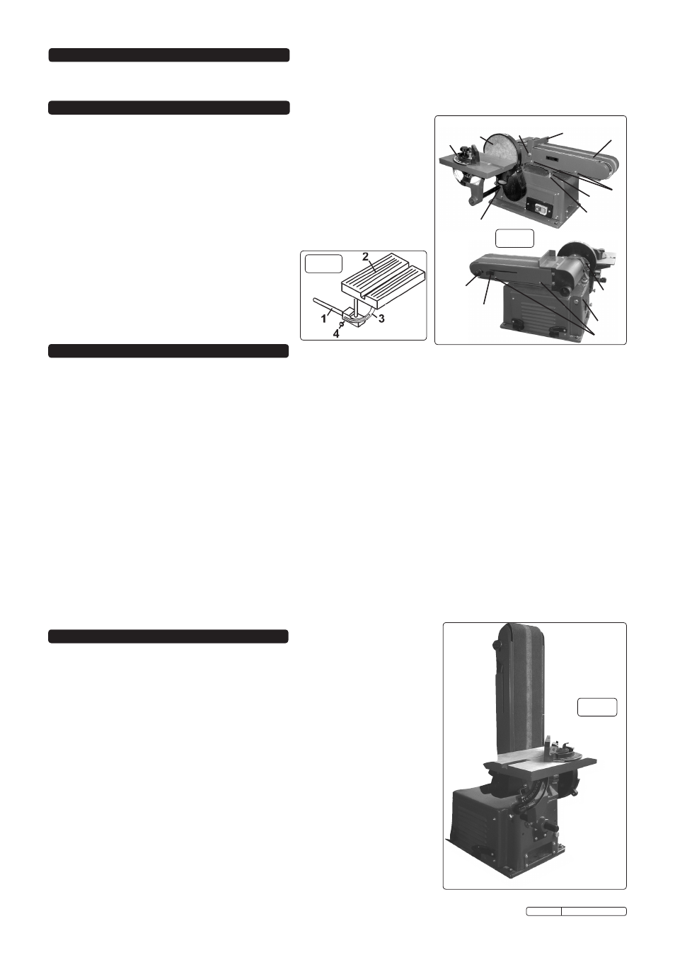
4.1.3. The sanding belt bed (fig.2.7) may be rotated through 90° from the horizontal and locked for operating in a vertical position (fig.3).
4.1.4. To alter the bed angle, remove the end guard by removing bolt (fig.2.8) and two screws on topside of guard, withdraw guard (fig.2.9).
4.1.5 Loosen the clamp nut (fig.2.10) located adjacent to upper pulley (behind sanding disc at rear). Pull the sanding belt upright and tighten
the lock nut. Fit the sanding table to mount (fig.2.11) and adjust to the desired angle. When returning to horizontal position ensure you
replace the guard.
4.2.
SANDING TABLE.
4.2.1. The table may be tilted through 45° by loosening thumb screw (fig.1.4).
4.2.2. When operating sanding bed in the vertical position (fig.3), mount sanding table at the foot of the belt:
a. Remove table assembly and support rod (fig.1.1) from the sanding disc position.
b. Insert table support rod (fig.1.1) into rear mounting boss (fig.2.11) and fix with locking bolt.
c. Align table as required and tighten all bolts.
4. OPERATING INSTRUCTIONS
5. MAINTENANCE
fig.1
fig 3
WARNING! Disconnect sander from the electrical supply before performing any
service or maintenance.
5.1.
Keep the sander clean and replace a worn or damaged sanding belt or disc.
5.2.
To change sanding belt remove the guard (fig.2.9), remove the bottom tray by
removing the four screws (fig.2.12).
5.3.
Push belt tension lever (fig.2.13) fully to the right. Remove the old belt. Place the new
belt over the two drums (note direction arrows on the inside of the belt). Move the
tension lever back to the left.
Replace guard and bottom tray and then adjust belt tracking if necessary.
5.4.
Replacing sanding disc pad. Remove table and disc guard. Peel the backing off pad,
and stick the new pad in place.
5.5.
Periodically lubricate the drive bearings.
DO NOT lubricate motor bearing. The motor
is a sealed unit.
Replacement Sanding Belts:
Replacement Sanding Disc:
SM14/B060G:
60Grit
SM14/D080G:
80Grit
SM14/B100G:
100Grit
4
13
5
6
1
7
8
12
12
11
10
2
9
3
fig.2
Original Language Version
SM14.V5 Issue: 4 - 07/03/12