Sealey WD302 User Manual
Wd302.v2, Fixed frame crane, Instructions for
Page 1
WD302.V2 - Issue: 1 - 19/06/08
InstructIons for:
FIXED FRAME CRANE
MoDEL no:
WD302.V2.
thank you for purchasing a sealey product. Manufactured to a high standard this product will, if used according to these instructions
and properly maintained, give you years of trouble free performance.
IMPORTANT: PLEASE READ THESE INSTRUCTIONS CAREFULLY. NOTE THE SAFE OPERATIONAL REQUIREMENTS, WARNINGS & CAUTIONS.
USE THE PRODUCT CORRECTLY AND WITH CARE FOR THE PURPOSE FOR WHICH IT IS INTENDED. FAILURE TO DO SO MAY CAUSE
DAMAGE OR PERSONAL INJURY AND WILL INVALIDATE THE WARRANTY. PLEASE KEEP INSTRUCTIONS SAFE FOR FUTURE USE.
2. GENERAL
1. CONTENTS
section 2. General. . . . . . . . . . . . . . . . . . . . . . . . . . . . . . . . . . . . .1.
section 2.1. Identification . . . . . . . . . . . . . . . . . . . . . . . . . . . . . . . . .1.
section 2.2. technical Data. . . . . . . . . . . . . . . . . . . . . . . . . . . . . . . .1.
section 3. safety/operational Instructions. . . . . . . . . . . . . . . . . . .2.
section 4. Maintenance/Examination/Inspection. . . . . . . . . . . . . .2.
section 5. Assembly/storage and priming. . . . . . . . . . . . . . . . . . .3.
section 6. owner’s & operator’s responsibilities. . . . . . . . . . . . .3.
section 7. Declaration of conformity. . . . . . . . . . . . . . . . . . . . . . .4.
section 8. Parts List/Diagram . . . . . . . . . . . . . . . . . . . . . . . . . . . .5.
Page No.
2.1.
Identification
supplier:
sealey Power Products,
Kempson Way,
suffolk Business Park,
Bury st Edmunds,
suffolk, IP32 7Ar.
Model no: WD302.V2
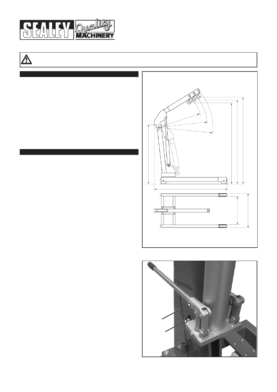
2.2. Technical Data
Rated Capacity
safe Working Load (sWL) 3t (tested to 50% overload).
Working Load Limit (WLL) 3t (tested to 50% overload).
Lifting cap. in Position 1: . . . . . . . . . . . . . . 3000kg
Lifting cap. in Position 2: . . . . . . . . . . . . . . 2500kg
Lifting cap. in Position 3: . . . . . . . . . . . . . . 2300kg
Maximum Lift Ht. at Minimum Jib Extn: . . . 2760mm
Maximum Lift Ht. at Maximum Jib Extn: . . . 2920mm
Length of Jib Position 1: . . . . . . . . . . . . . . . 1620mm
Length of Jib Position 2: . . . . . . . . . . . . . . . 1765mm
Length of Jib Position 3: . . . . . . . . . . . . . . . 1910mm
Height of frame: . . . . . . . . . . . . . . . . . . . . . 265mm
Length of frame: . . . . . . . . . . . . . . . . . . . . 2150mm
overall Height: . . . . . . . . . . . . . . . . . . . . . . 2000mm
Maximum Width of frame: . . . . . . . . . . . . . 1290mm
Width Inside frame: . . . . . . . . . . . . . . . . . . 1120mm
Weight: . . . . . . . . . . . . . . . . . . . . . . . . . . . . 302kg
a)
Design capability: test Load 50% overload.
b)
for a description of in-service and out-of-service conditions see
section 3 safety, section 4 Maintenance and section 6.
c)
the crane is fitted with a bypass valve that will prevent the ram
from over extending.
d)
for applications see section 3 safety.
e)
for control system, see fig.1 for release valve and pump handle
assy. usage is explained in section 3.2 operation.
f)
for ground condition requirements, see section 3 safety.
g)
for information on parts and materials requiring specialised
repair techniques see section 4 Maintenance.
fig.1
rELEAsE
VALVE
PuMP
HAnDLE
AssY.
1910mm
1765mm
2920mm
2840mm
1290mm
1120mm
265mm
2000mm
2760mm
1620mm
2150mm
3000kg Max.
2500kg Max.
2300kg Max.