Fig.1, Fig.2, Assembly – Sealey YAJ10-25LR User Manual
Page 2: Air supply
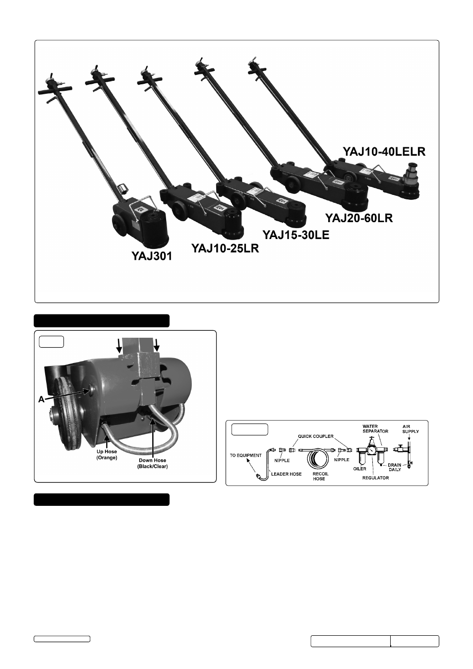
4. aSSEMBLy
4.1.
attaching the handle
4.1.1. Remove a circlip from either side of the large pin (fig.1A).
4.1.2. Slide out the pin and place the handle into the opening. Slide
the pin back through the jack, lining up the handle and through
the other side. Secure with circlips.
4.2.
air hoses
4.2.1. Screw in the two air hoses from the handle into the jack.
4.2.2. The hose marked orange must be screwed into the left-hand
side. The hose marked black or clear into the right-hand side (fig.1).
4.2.3. Ensure the hoses are tight and do not obstruct the movement
of the handle.
fig.1
5. aIR SuPPLy
5.1. Ensure that the jack pneumatic switch is in the "off" position before connecting to the air supply.
5.2. You will require an air pressure of between 116psi and 174psi and an air flow of 11.5cfm (10.5cfm for YAJ301) to get the best
performance from this jack.
5.3. WaRnInG! Ensure the air supply does not exceed thestated maximum pressurewhile operating the jack.
Too high an air pressure and unclean air will shorten the products life due to excessive wear, and may be dangerous causing possible
damage and personal injury.
5.4. Drain the air tank daily. Water in the air line will damage the jack.
5.5. Clean the air inlet filter screen weekly.
5.6. Keep the air hose between the compressor and the air jack as short as possible, and install an air filter and oiler (fig.2).
5.7. Line pressure should be increased to compensate for unusually long air hoses (over 8 metres). The minimum hose diameter should be
3/8" I.D. and fittings must have the same inside dimensions.
5.8. Keep hose away from heat, oil and sharp edges. Check hoses for wear, and make certain that all connections are secure.
fig.2
YAJ301,YAJ10-25LR,YAJ15-30LE Issue 1-29/04/13
YAJ20-60LR, YAJ10-40LELR
© Jack Sealey Limited
Original Language Version