Sealey SJBEX200LP User Manual
Sjbex200lp, Jacking beam, Fig.1
InstructIons for:
JACKING BEAM
Model:
SJBEX200LP
thank you for purchasing a sealey Product. Manufactured to a high standard this product will, if used according to these instructions and
properly maintained, give you years of trouble free performance.
Important: REAd thESE INStRuCtIoNS CAREfuLLy. NotE thE SAfE oPERAtIoNAL REQuIREMENtS, WARNINGS ANd CAutIoNS.
uSE thIS JACK CoRRECtLy ANd WIth CARE foR thE PuRPoSE foR WhICh It IS INtENdEd. fAILuRE to do So MAy CAuSE dAMAGE
ANd/oR PERSoNAL INJuRy ANd WILL INvALIdAtE thE WARRANty. REtAIN thESE INStRuCtIoNS foR futuRE uSE.
1. SAfEty PRECAutIoNS
2. SPECIfICAtIoNS
clearance. fitted with large diameter roller support arms for use on
lifts with inner rail type configuration. ultra wide configuration arms
extend to 1.6mtr and feature adjustable saddles with interchangeable
height posts (optional). tried and tested hydraulic system with double
stroke pump and two-stage mechanical safety lock for added safety.
Model . . . . . . . . . . . . . . . . . . . . . . . . . . . . . . . . . . . . . . SJBEX200LP
capacity:. . . . . . . . . . . . . . . . . . . . . . . . . . . . . . . . . . . . . . . . . . . .2ton
support Arm reach:. . . . . . . . . . . . . . . . . . . . . . . . . . 720 - 1075mm
Beam lift: . . . . . . . . . . . . . . . . . . . . . . . . . . . . . . . . . . . . 35 - 38 0mm
load Arm reach: . . . . . . . . . . . . . . . . . . . . . . . . . . . . 760 - 1650mm
net Weight:. . . . . . . . . . . . . . . . . . . . . . . . . . . . . . . . . . . . . . . . . 97kg
optional Accessories
extension lift Adaptor 60mm (Pair): . . . . . . . . . . . . . sJBeXlP060A
extension lift Adaptor 100mm (Pair): . . . . . . . . . . . . sJBeXlP100A
flat Arm set - spring loaded: . . . . . . . . . . . . . . . . . . . sJBeXlPflA
ensure the beam is in sound condition and good working order.
take action for immediate repair or replacement of damaged parts.
Use genuine parts only. The use of improper parts may be
dangerous and will invalidate the warranty.
consult the vehicle manufacturer for the correct lifting locations.
Inspect the beam before each use. do not use the beam if it is
damaged, altered, modified, in poor condition, leaking hydraulic
fluid, or unstable due to missing parts.
use the beam only for its intended purpose.
Make sure the vehicle is in park and the hand brake is on before
attempting to raise the vehicle.
the beam can only be used to lift one end of the vehicle.
do not lift using the central portion of the unit if the work to be
performed can cause the load to move.
Always lower load slowly and carefully.
only use saddles made by the manufacturer.
do not alter or modify this beam in any way.
do not load the beam beyond its rated capacity.
do not operate the beam if damaged.
do not allow untrained persons to operate the beam.
When not in use store beam fully lowered.
ensure all non-essential persons keep a safe distance whilst the
beam is in use.
ensure that there are no persons or obstructions beneath the
vehicle before lowering.
use a qualified person to maintain or repair the beam’s hydraulic
system.
this is a lifting device only. Make sure the load is centered on
saddles before lifting.
Be sure setup is stable and secure before lifting. Be careful of
pinch points.
do not use the beam for purposes other than that for which it is
intended.
do not top up hydraulic system with brake fluid. use hydraulic
jack oil only.
WarnInG! Failure to heed these precautions may result in
loss of load, damage to beam and/or personal injury.
3. CoNtRoLS
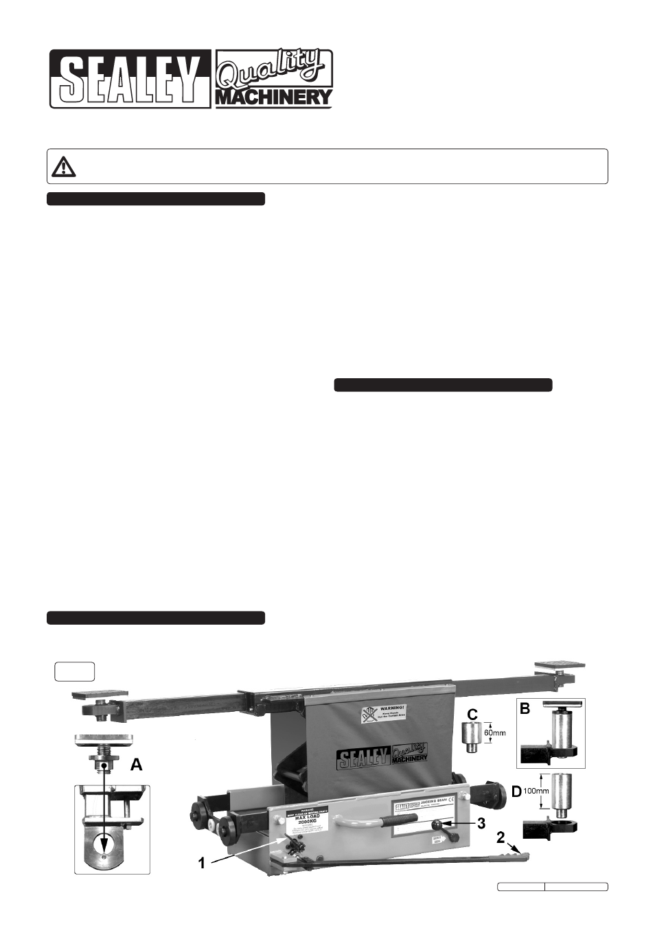
fig.1
3.1.
Jacking beam controls (fig.1).
3.1.1 familiarise yourself with the controls of the jacking beam
before operating. Note: The further anticlockwise you turn the
release valve (1) the faster the beam will lower. Familiarise
yourself with this before operating under load.
3.1.2 to raise the jack, pump the jacking lever (2) horizontally
towards and away from the face of the unit.
3.1.3 As a safety feature the beam has two locking positions which
are controlled by the locking lever (3).
3.1.4 When jacking, the locking lever will engage at certain heights
(approx 150mm and 300mm of lift height) to prevent the jack
from lowering all the way should the release valve be
accidentally moved. to lower the jack past this point you
must raise the jack a small amount and then turn and hold
the locking lever (3) clockwise whilst turning the release
valve anticlockwise.
3.2.
Accessories (fig.1).
3.2.1 the lift is supplied with two adjustable saddles (see 'A').
ensure that the flat area on the saddle sleeve is aligned with
the protruding area in the hole in the saddle recess.
3.2.2 two sizes of height extension posts are available as optional
extras (60 and 100mm) as shown at 'c' and 'd' below.
3.2.3 the posts can be used singly (see 'B' below) or together for
a maximum height extension of 160mm.
low profile design permits use on lifts mounted in pits and commonly
used in Atl's. Also permits use on vehicles with low ground
Original Language Version
sJBeX200lP Issue: 3 - 16/10/09