Sealey ES500 User Manual
Es500.v2, Engine support beam 500kg model no
Thank you for purchasing a Sealey Product. Manufactured to a high standard this product will, if used according to these instructions
and properly maintained, give you years of trouble free performance.
IMPORTANT: PLEASE READ THESE INSTRUCTIONS CAREFULLY. NOTE THE SAFE OPERATIONAL
REQUIREMENTS, WARNINGS AND CAUTIONS. USE THIS PRODUCT CORRECTLY AND WITH CARE FOR THE
PURPOSE FOR WHICH IT IS INTENDED. FAILURE TO DO SO MAY CAUSE DAMAGE AND/OR PERSONAL INJURY,
AND WILL INVALIDATE THE WARRANTY. PLEASE KEEP INSTRUCTIONS SAFE FOR FUTURE USE.
Instructions for:
ENGINE SUPPORT BEAM 500kg
Model No:
ES500.V2
Ensure that the engine support is in good working order. Take action for immediate repair or replacement of
damaged parts. Use genuine parts only. The use of unauthorised parts may be dangerous and will invalidate
the warranty.
Locate the vehicle in a suitable, well lit work area.
Keep work area clean and tidy and free from unrelated materials.
Ensure the vehicle handbrake is engaged and the engine/motor is switched off.
Ensure all non-essential persons keep a safe distance whilst the engine support is in use.
DO NOT use the engine support if damaged.
DO NOT allow untrained persons to operate the engine support.
DO NOT use the engine support for purposes other than that for which it is designed.
DO NOT exceed the rated capacity of the engine support.
When not in use, store engine support in a safe, dry, childproof area.
1. SAFETY INSTRUCTIONS
2. INTRODUCTION & SPECIFICATION
2.1. Designed to support and accurately position engines
during maintenance operations such as replacing antivibration
mountings and certain body panels. Also used as an aid for
the removal of gearboxes and transmissions. Beams
supported on rubber feet and fine adjustment control is
obtained by using screw/hook mechanism. Supplied with a
short length of chain.
4. OPERATING INSTRUCTIONS
3. ASSEMBLY INSTRUCTIONS
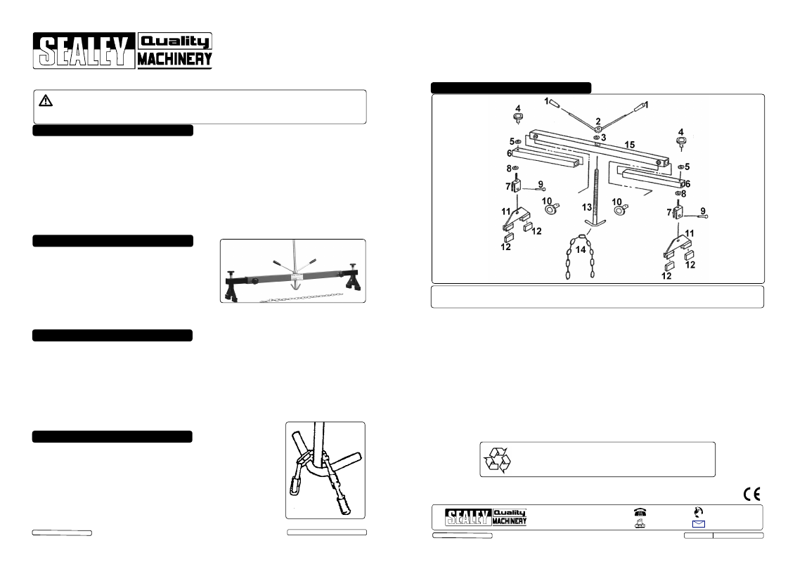
Note: Numbers in brackets refer to item numbers shown in the parts diagram.
3.1. Insert the telescopic beam (6) into the beam (15) and secure using the grip (10).
3.2. Remove the grip (4) and washer (5) from the standing block (7), pass the threaded section of the standing
block through the hole in the telescopic beam (6) and secure using the washer (5) and grip (4).
3.3. Remove the bolt and locknut (9) from the standing block (7), insert the foot assembly (11) and secure
using the bolt and locknut (9).
3.4. Repeat paragraphs 3.1 to 3.3 at the other end of the beam (15).
3.5. Slot the threaded section of the adjustable screw (13) up through the centre hole in the beam (15), fit the
washer (3) and secure using the operating clamp assembly (2).
3.6. The engine support is now ready for use.
Note: Ensure all grips and nuts are tightened before applying a load.
Note: Numbers in brackets refer to item numbers shown in the parts diagram.
4.1. Ensure the adjustable screw (13) is wound to its highest position to prevent
damage whilst locating the engine support over an engine bay.
4.2. Ensure the grips (4 & 10) are loose and locate the rubber blocks (12) in the
gutters of the vehicle’s front wing panels or close to the suspension strut towers.
4.3. Attach the ends of the chain to the lifting brackets on the engine. Note: Refer
to manufacturer’s handbook to identify lifting brackets.
4.4. Lower the adjustable screw and hook the chain around the hook as shown in
fig.1.
2.2. Maximum Capacity. . . . . . . . . . . 500kg
Minimum Width . . . . . . . . . . . . . 1120mm
Maximum Width . . . . . . . . . . . 1910mm
Screw Travel . . . . . . . . . . . . . . . . 230mm
Weight
. . . . . . . . . . . . . . . . .
14.02kg
Fig.1
ES500.V2 Issue: 1 - 26/06/13
Original Language Version
© Jack Sealey Limited
4.5. Tighten all four grips (4 & 10) and all nuts.
4.6. Rotate the operating clamp assembly to tighten the chain and support the engine.
4.7. On completion of the maintenance task, rotate the operating clamp assembly to release the tension on the
chain.
4.8. Unhook the chain, loosen both grips (4 & 10) and remove the engine support from the vehicle.
4.9. Remove the chain from the engine lifting points.
5. PARTS
Item Description
1
Grip (handle bar)
2
Operating clamp assy.
3
Washer 22mm internal Ø
4 Grip
5
Washer 11mm internal Ø
6
Telescopic beam
7
Standing block
8
Washer 21mm internal Ø
9
Bolt & Locknut 16mm
10
Grip (small)
11 Foot
12
Rubber block
13
Adjustable screw
14 Chain
15 Beam
NOTE: It is our policy to continually improve products and as such we reserve the right to alter data, specifications and component parts without prior notice.
IMPORTANT: No liability is accepted for incorrect use of this product.
WARRANTY: Guarantee is 12 months from purchase date, proof of which will be required for any claim.
INFORMATION: For a copy of our latest catalogue and promotions call us on 01284 757525 and leave your full name and address, including postcode.
01284 757500
01284 703534
Sole UK Distributor, Sealey Group,
Kempson Way, Suffolk Business Park
,
Bury St. Edmunds, Suffolk,
IP32 7AR
www.sealey.co.uk
W e b
Original Language Version
Environmental Protection.
Recycle unwanted materials instead of disposing of them as waste.
All tools, accessories and packaging should be sorted, taken to a recycle
centre and disposed of in a manner which is compatible with the environment.
ES500.V2 Issue: 1 - 26/06/13
© Jack Sealey Limited
Parts support is available for this product. To obtain a listing and/or diagram, please log on to:www.sealey.co.uk,
email: [email protected]