Sealey ES300A User Manual
Operating instructions, Assembly instructions, Fig.1
Thank you for purchasing a Sealey Product. Manufactured to a high standard this product will, if used according to these instructions
and properly maintained, give you years of trouble free performance.
IMPORTANT: PLEASE READ THESE INSTRUCTIONS CAREFULLY. NOTE THE SAFE OPERATIONAL
REQUIREMENTS, WARNINGS AND CAUTIONS. USE THIS PRODUCT CORRECTLY AND WITH CARE FOR THE
PURPOSE FOR WHICH IT IS INTENDED. FAILURE TO DO SO MAY CAUSE DAMAGE AND/OR PERSONAL
INJURY, AND WILL INVALIDATE THE WARRANTY. PLEASE KEEP INSTRUCTIONS SAFE FOR FUTURE USE.
Instructions For:
ENGINE SUPPORT BEAM 300kg
ALUMINIUM
Model No:
ES300A
Ensure that the engine support is in good working order.
Take action for immediate repair or replacement of
damaged parts. Use genuine parts only.
The use of unauthorised parts may be dangerous and will
invalidate the warranty.
Locate the vehicle in a suitable, well lit work area.
Keep work area clean and tidy and free from unrelated materials.
Ensure the vehicle handbrake is engaged and the engine/motor is switched off.
Ensure all non-essential persons keep a safe distance whilst the engine support is in use.
DO NOT use the engine support if damaged.
DO NOT allow untrained persons to operate the engine support.
DO NOT use the engine support for purposes other than that for which it is designed.
DO NOT exceed the rated capacity of the engine support.
When not in use, store engine support in a safe, dry, childproof area.
1. SAFETY INSTRUCTIONS
2. INTRODUCTION & SPECIFICATION
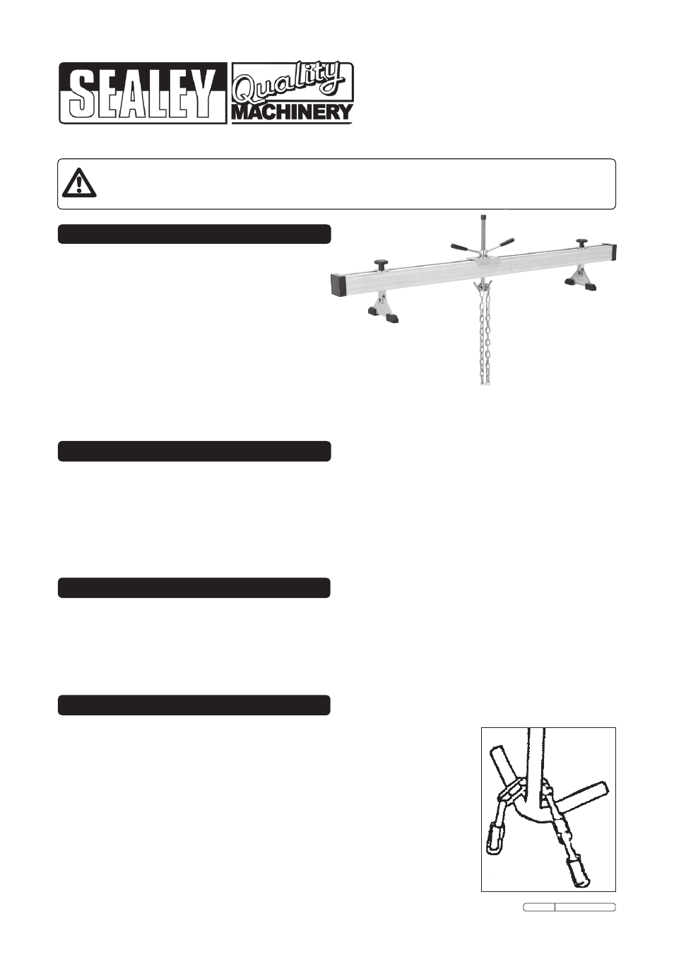
Designed to support and accurately position engines during maintenance operations such as replacing anti-vibration mountings
and certain body panels. Lightweight aluminium, weighs only 8.7kg making it easy to manoeuvre, without compromising the
maximum capacity. Also used as an aid for the removal of gearboxes and transmissions. Beams supported on rubber feet and
fine adjustment control is obtained by using a screw/hook mechanism. Supplied with a short length of chain.
4. OPERATING INSTRUCTIONS
3. ASSEMBLY INSTRUCTIONS
3.1.
Follow the diagrams Fig.2, 3, 4 & 5 overleaf to assemble your ES300A Engine Support.
3.2.
Ensure the Adjustable Screw Fig.2 is lightly oiled before use.
3.3.
Ensure the Adjustable Screw Bearing Fig.2 is greased before use.
Note: Ensure all fixings are tightened before applying a load.
4.1. Ensure the adjustable screw is wound to its highest position to prevent damage whilst
locating the engine support over an engine bay.
4.2. Ensure the foot screws are loose and locate the rubber blocks in the gutters of the
vehicle’s front wing panels or close to the suspension strut towers.
4.3. Attach the ends of the chain to the lifting brackets on the engine.
Note: Refer to manufacturer’s handbook to identify lifting brackets.
4.4. Lower the adjustable screw and hook the chain around the hook as shown in fig.1.
4.5. Tighten both foot screws.
4.6. Rotate the adjustable screw assembly clockwise to tighten the chain and support the
engine.
4.7. On completion of the maintenance task, rotate the adjustable screw assembly
anti-clockwise to release the tension on the chain.
4.8. Unhook the chain and remove the engine support from the vehicle.
4.9. Remove the chain from the engine lifting points.
Maximum Capacity. . . . . . . . . . . 300kg
Minimum Width . . . . . . . . . . . . . . 180mm
Maximum Width . . . . . . . . . . . 1400mm
Screw Travel . . . . . . . . . . . . . . . . 155mm
Fig.1
Original Language Version
ES300A Issue: 1 - 18/02/10