Sealey ES600 User Manual
Es600, Universal engine support model, Instructions for
ES600 - 1 - 251002
Thank you for purchasing a Sealey Product. Manufactured to a high standard this product will, if used according to these instructions
and properly maintained, give you years of trouble free performance.
IMPORTANT:
PLEASE READ THESE INSTRUCTIONS CAREFULLY. NOTE THE SAFE OPERATIONAL
REQUIREMENTS, WARNINGS AND CAUTIONS. USE THIS PRODUCT CORRECTLY AND WITH CARE FOR THE
PURPOSE FOR WHICH IT IS INTENDED. FAILURE TO DO SO MAY CAUSE DAMAGE AND/OR PERSONAL INJURY,
AND WILL INVALIDATE THE WARRANTY. PLEASE KEEP INSTRUCTIONS SAFE FOR FUTURE USE.
Instructions For:
UNIVERSAL ENGINE SUPPORT
Model:
ES600
3 Ensure that the engine support is in good working order. Take action for immediate repair or replacement of
damaged parts. Use genuine parts only. The use of unauthorised parts may be dangerous and will invalidate
the warranty.
3 Locate the vehicle in a suitable, well lit work area.
3 Keep work area clean and tidy and free from unrelated materials.
3 Ensure the vehicle handbrake is engaged and the engine/motor is switched off.
3 Ensure all non-essential persons keep a safe distance whilst the engine support is in use.
7 DO NOT use the engine support if damaged.
7 DO NOT allow untrained persons to operate the engine support.
7 DO NOT use the engine support for purposes other than that for which it is designed.
7 DO NOT exceed the rated capacity of the engine support.
3 When not in use, store engine support in a safe, dry, childproof area.
1. SAFETY INSTRUCTIONS
2.
INTRODUCTION & SPECIFICATION
2.1. The ES600 is suitable for heavy engines including
6-cylinder variants. Supports engine during maintenance
operations including engine mounting replacement.
Beam is supported on 2 rubber covered feet with 3rd,
height adjustable foot resting on the front of the vehicle.
Supplied with 2 short lifting chains.
4. OPERATING INSTRUCTIONS
3. ASSEMBLY INSTRUCTIONS
Note: Numbers in brackets refer to item numbers shown in the parts diagram.
3.1. Slide the moveable beam assembly (11) onto the beam (1).
3.2. Slide the two moveable beams (7) into position as required. Note: The moveable beams (7) can be fitted
either side of the moveable beam assembly (11), as shown in fig.1. or one can be fitted to the moveable
beam assembly (11).
3.3. Adjust the position of the moveable beams (7) to provide the optimum weight distribution.
3.4. Remove the bolts and washers (4 & 2) from the ends of the beam (1) and telescopic beam (16). Fit the
standing platform assemblies (3) and secure using the bolts and washers previously removed.
3.5. Slide the telescopic beam (16) inside the beam (1).
3.6. Remove the pin (13) from the support arm (15), slide the telescopic beam assembly (12) onto the support
arm, adjust for the required position and secure by fitting the pin through both items.
3.7. Slide the telescopic beam assembly (12) into the moveable beam assembly (11).
3.8. Remove the nut (5) and washer (6) from both J hooks (8), insert the J hooks through the locating tubes
on the moveable beams and refit the washers and nuts.
3.9. The engine support is now ready for use.
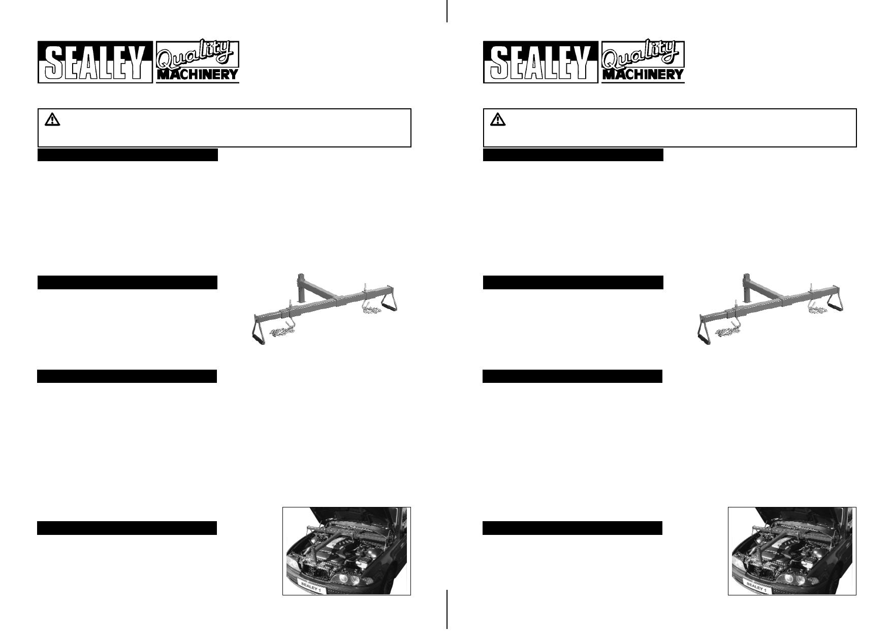
Note: Numbers in brackets refer to item numbers shown in the parts
diagram.
4.1. Position the support beam over the engine with the standing
platform assemblies (3) in the gutters of the wing panels, or close to
the suspension strut towers and the support arm positioned on the
front cross member of the car, as shown in fig.2.
2.2. Maximum Capacity . . . . . . . . . .600kg
Length min/max . . . . . . . . .600/*875mm
Width min/max . . . . . .1010/*1210mm
* Allows 200mm safety margin
Fig. 1
Fig. 2
ES600 - 1 - 251002
Thank you for purchasing a Sealey Product. Manufactured to a high standard this product will, if used according to these instructions
and properly maintained, give you years of trouble free performance.
IMPORTANT:
PLEASE READ THESE INSTRUCTIONS CAREFULLY. NOTE THE SAFE OPERATIONAL
REQUIREMENTS, WARNINGS AND CAUTIONS. USE THIS PRODUCT CORRECTLY AND WITH CARE FOR THE
PURPOSE FOR WHICH IT IS INTENDED. FAILURE TO DO SO MAY CAUSE DAMAGE AND/OR PERSONAL INJURY,
AND WILL INVALIDATE THE WARRANTY. PLEASE KEEP INSTRUCTIONS SAFE FOR FUTURE USE.
Instructions For:
UNIVERSAL ENGINE SUPPORT
Model:
ES600
3 Ensure that the engine support is in good working order. Take action for immediate repair or replacement of
damaged parts. Use genuine parts only. The use of unauthorised parts may be dangerous and will invalidate
the warranty.
3 Locate the vehicle in a suitable, well lit work area.
3 Keep work area clean and tidy and free from unrelated materials.
3 Ensure the vehicle handbrake is engaged and the engine/motor is switched off.
3 Ensure all non-essential persons keep a safe distance whilst the engine support is in use.
7 DO NOT use the engine support if damaged.
7 DO NOT allow untrained persons to operate the engine support.
7 DO NOT use the engine support for purposes other than that for which it is designed.
7 DO NOT exceed the rated capacity of the engine support.
3 When not in use, store engine support in a safe, dry, childproof area.
1. SAFETY INSTRUCTIONS
2.
INTRODUCTION & SPECIFICATION
2.1. The ES600 is suitable for heavy engines including
6-cylinder variants. Supports engine during maintenance
operations including engine mounting replacement.
Beam is supported on 2 rubber covered feet with 3rd,
height adjustable foot resting on the front of the vehicle.
Supplied with 2 short lifting chains.
4. OPERATING INSTRUCTIONS
3. ASSEMBLY INSTRUCTIONS
Note: Numbers in brackets refer to item numbers shown in the parts diagram.
3.1. Slide the moveable beam assembly (11) onto the beam (1).
3.2. Slide the two moveable beams (7) into position as required. Note: The moveable beams (7) can be fitted
either side of the moveable beam assembly (11), as shown in fig.1. or one can be fitted to the moveable
beam assembly (11).
3.3. Adjust the position of the moveable beams (7) to provide the optimum weight distribution.
3.4. Remove the bolts and washers (4 & 2) from the ends of the beam (1) and telescopic beam (16). Fit the
standing platform assemblies (3) and secure using the bolts and washers previously removed.
3.5. Slide the telescopic beam (16) inside the beam (1).
3.6. Remove the pin (13) from the support arm (15), slide the telescopic beam assembly (12) onto the support
arm, adjust for the required position and secure by fitting the pin through both items.
3.7. Slide the telescopic beam assembly (12) into the moveable beam assembly (11).
3.8. Remove the nut (5) and washer (6) from both J hooks (8), insert the J hooks through the locating tubes
on the moveable beams and refit the washers and nuts.
3.9. The engine support is now ready for use.
2.2. Maximum Capacity . . . . . . . . . .600kg
Length min/max . . . . . . . . .600/*875mm
Width min/max . . . . . .1010/*1210mm
* Allows 200mm safety margin
Fig. 1
Fig. 2
Note: Numbers in brackets refer to item numbers shown in the parts
diagram.
4.1. Position the support beam over the engine with the standing
platform assemblies (3) in the gutters of the wing panels, or close to
the suspension strut towers and the support arm positioned on the
front cross member of the car, as shown in fig.2.