Sealey ES350 User Manual
Es350.v2, Instructions for, Safety instructions 2. specification & assembly
Thank you for purchasing a Sealey product. Manufactured to a high standard this product will, if used according to these instructions
and properly maintained, give you years of trouble free performance.
1. SAFETY INSTRUCTIONS
2. SPECIFICATION & ASSEMBLY
IMPORTANT: PLEASE READ THESE INSTRUCTIONS CAREFULLY. NOTE THE SAFE OPERATIONAL REQUIREMENTS, WARNINGS AND CAUTIONS.
USE THIS PRODUCT CORRECTLY AND WITH CARE FOR THE PURPOSE FOR WHICH IT IS INTENDED. FAILURE TO DO SO MAY CAUSE
DAMAGE AND/OR PERSONAL INJURY AND WILL INVALIDATE THE WARRANTY. PLEASE KEEP INSTRUCTIONS SAFE FOR FUTURE USE.
INSTRUCTIONS FOR:
HEAVY DUTY E N G I N E S TA N D
Model No:
ES350.V2
ES350.V2 - 1 - 05/10/07
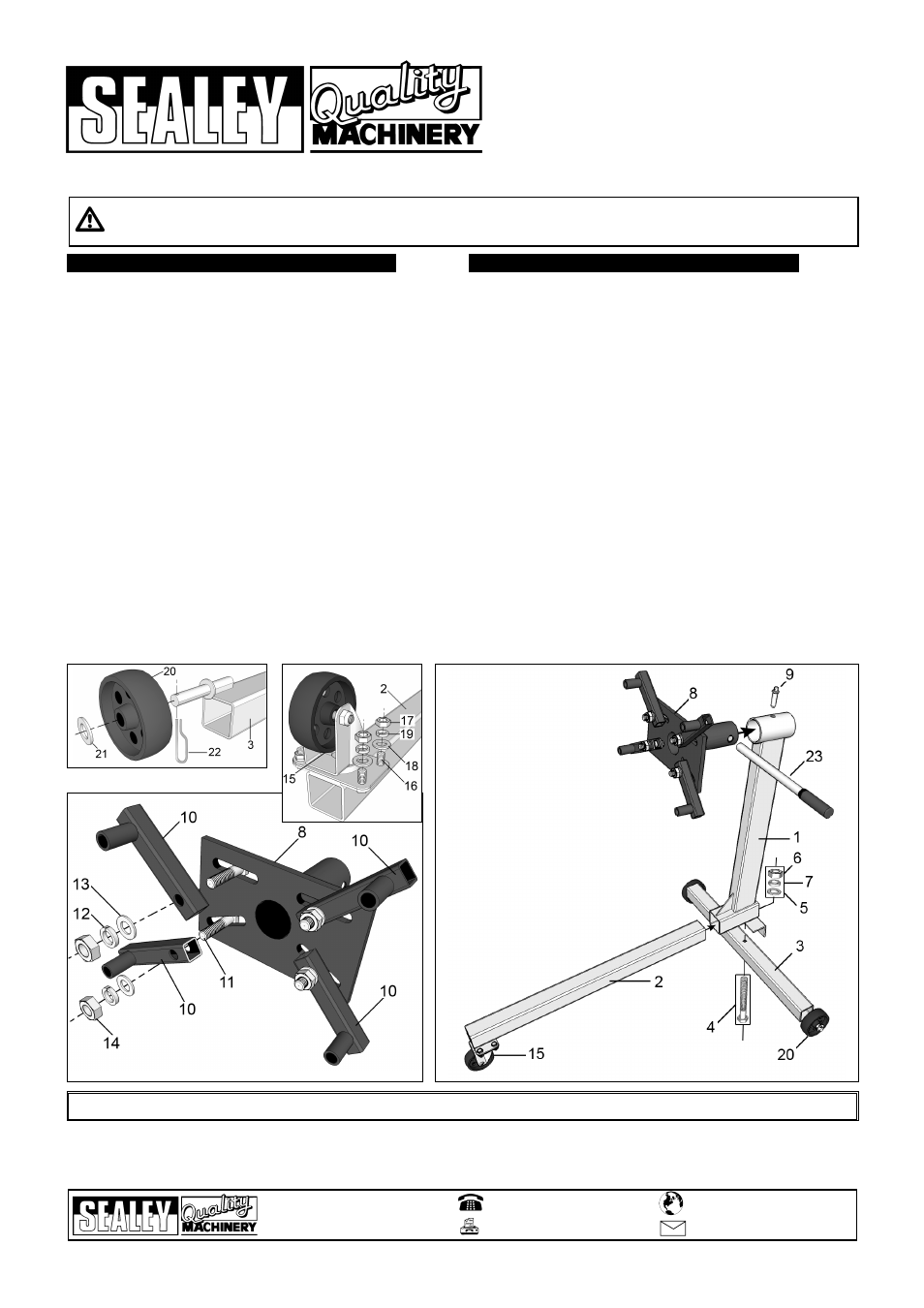
2.2
Assembly
2.2.1. Referring to fig.1, slide a wheel (20) onto each axle stub at either end of
the axle leg (3). Place an M16 axle washer (21) over each stub and
retain each wheel by pushing a spring clip (22) through the hole in the
end of each axle stub.
2.2.2. Referring to fig.2, bolt the castor (15) to the mounting plate at the end of
the front leg (2) using four M8 bolts (16), four M8 flat washers (18), four
lock washers (19) and four M8 nuts (17).
2.2.3 Referring to fig.3, attach the four engine mounting arms (10) to the
mounting plate (8) using four M14 bolts (11), four M14 flat washers (13),
four M4 lock washers (12) and four M14 nuts (14).
2.2.4 Assemble the main frame referring to fig,4 . Slide the front leg (2) into
the square tube at the base of the main post (1) ensuring that the castor
is facing downwards and the hole at the other end of the leg is aligned
with the hole in the bottom of the square tube. Insert the 70mm M8 bolt
(4) entirely through the axle leg (3) then bring the leg up underneath the
main post so that the protruding bolt appears inside the square tube. Fix
the three main components together using the M10 washer (5), M10
lock washer (7) and the M10 nut (6) and tighten firmly.
2.2.5. Take the engine mounting plate assembly and insert the tubular section
through the tube at the top of the main post. Rotate the assembly so
that one of the six holes in the inner tube aligns with the single hole in
the top of the post. Insert the locking pin (9).
2.2.6. Insert the handle through the holes in the rear end of the engine
mounting plate tube.
2.1
Specification
Max capacity . . . . . . . . . . .350kg
Width . . . . . . . . . . . . . . .790mm
Length . . . . . . . . . . . . . . .890mm
Height . . . . . . . . . . . . . . .920mm
Weight . . . . . . . . . . . . . . .16.5kg
01284 757500
01284 703534
Sole UK Distributor
Sealey Group,
Bury St. Edmunds, Suffolk.
www.sealey.co.uk
Web
NOTE:
It is our policy to continually improve products and as such we reserve the right to alter data, specifications and component parts without prior notice.
IMPORTANT: No liability is accepted for incorrect use of this product.
WARRANTY: Guarantee is 12 months from purchase date, proof of which will be required for any claim.
INFORMATION: For a copy of our catalogue and latest promotions call us on 01284 757525 and leave your full name, address and postcode.
!
WARNING! Ensure all Health and Safety, local authority, and general workshop
practice regulations are strictly adhered to when using this equipment.
"
DO NOT use unit if damaged.
#
Replace or repair damaged parts. Use recommended parts only.
Unauthorised parts may be dangerous and will invalidate the warranty.
#
Keep the stand clean for best and safest performance.
#
Locate the stand in a suitable work area. Keep area clean and tidy and free
from unrelated materials. Ensure there is adequate lighting.
#
Use on a firm, level surface capable of sustaining the stand and the load.
#
Maintain correct balance and footing. Ensure the floor is not slippery and
wear non-slip shoes.
#
Ensure all non-essential persons keep a safe distance whilst the stand is in use.
#
Lock mounting plate in position with locking pin before fixing a load and
ensure the load is centred and securely mounted on the mounting plate.
#
When an engine is mounted, take the weight of the engine on the handle
before removing the locking pin.
#
Ensure the stand and load are stable.
#
To move a loaded stand, steady the load and push from behind the main
post of the stand so that the castor wheel is ahead of the load.
"
DO NOT pull the unit backwards, or push from the side, as this may
cause the stand to tip.
#
Ensure surface over which the stand is to travel is strong enough to take
the stand and load and that it is not cracked, uneven or obstructed.
"
DO NOT allow untrained persons to use the stand.
"
DO NOT exceed the rated capacity of 350kg.
$
DANGER! DO NOT work under an engine mounted on the stand.
"
DO NOT use the stand for purposes other than those for which it is designed.
CONTENTS
ITEM DESCRIPTION
NO.
1
MAIN POST
1
2
FRONT LEG
1
3
AXLE LEG
1
4
BOLT, M10 X 70
1
5
WASHER, FLAT, M10
1
6
NUT, HEX., M10
1
7
WASHER, LOCK, M10
1
8
MOUNTING PLATE
1
9
LOCKING PIN
1
10
ENGINE MOUNTING ARM 4
11
BOLT, M14 X 60
4
12
WASHER, LOCK, M14
4
13
WASHER, FLAT, M14
4
14
NUT, HEX., M14
4
15
CASTOR
1
16
BOLT, M8 X 16
4
17
NUT, M8
4
18
WASHER, M8
4
19
LOCK WASHER, M8
4
20
REAR WHEEL
2
21
WASHER, FLAT, M16
2
22
SPRING PIN
2
23
HANDLE
1
fig.4
fig.3
fig.2
fig.1
Parts support is available for this product. To obtain a parts listing and/or diagram,
please log on to www.sealey.co.uk, email [email protected] or phone 01284 757500.