Sealey WD80 User Manual
Wd80, Wheel removal-lifter trolley (80kg) yankee, Fig.1 fig.2
InstructIons for:
WHEEL REMOVAL-LIFTER
TROLLEY (80kg) YANKEE
MoDEL no:
WD80
thank you for purchasing a sealey product. Manufactured to a high standard this product will, if used according to these instructions and
properly maintained, give you years of trouble free performance.
1. SAFETY INSTRUCTIONS
IMPORTANT: PLEASE READ THESE INSTRUCTIONS CAREFULLY. NOTE THE SAFE OPERATIONAL REQUIREMENTS, WARNINGS AND
CAUTIONS. USE THE PRODUCT CORRECTLY AND WITH CARE FOR THE PURPOSE FOR WHICH IT IS INTENDED. FAILURE TO DO SO MAY
CAUSE DAMAGE AND/OR PERSONAL INJURY AND WILL INVALIDATE THE WARRANTY. PLEASE KEEP INSTRUCTIONS SAFE FOR FUTURE USE.
2. INTRODUCTION & SPECIFICATION
Always lower, centre and use slide bar and safety rod before attempting to
move trolley.
only use the trolley on firm, level, unobstructed surfaces which are
capable of supporting the trolley and wheel.
Do not overload the trolley - maximum capacity is
80kg.
Do not allow others to ride on the trolley.
Do not use on tarmacadam. the trolley must only be used on a concrete
surface.
WD80 is fitted with locking castors, these are for use at the operator's
discretion and when the trolley is left unattended.
replace or repair damaged parts. Use only recommended parts.
Unauthorised parts may be dangerous and will invalidate the warranty.
use a qualified person to lubricate and maintain the trolley. Do not use
brake fluid to top up hydraulic unit. use sealey hydraulic oil only.
Warning! failure to comply with these instructions may result in loss of
load, damage to trolley or other property and/or personal injury.
beam using three pairs of fixings, two pairs in the horizontal plane and
one pair in the vertical plane.
Warning! The warnings, cautions and instructions discussed in this
manual cannot cover all possible conditions and situations that may
occur. It must be understood that common sense and caution are
factors which cannot be built into this product, but must be applied
by the operator.
Long reach bottle jack type mechanism. steel construction with friction
mounted roller arms. front and rear castors for easy manoeuvrability.
Adjustable roller width, 300 or 360mm, gives great flexibility. supplied with
safety bar to prevent wheel from tipping forward.
Maximum Load ..............................................................................................80kg
Min. Lift Height ......................................................................................... 105mm
Max. Lift Height ........................................................................................ 930mm
Width Between rollers ..................................................................... 300, 360mm
roller Length ............................................................................................ 280mm
3. ASSEMbLY
Note: Numbers in diagrams correspond to the item numbers on the parts
diagram.
3.1
Assembling the castor base.
3.1.1 referring to fig.1, take one wheel beam (35) and attach a non-locking
castor (34) to the short wheel mounting plate using a locking washer
(33) and nut (32). Attach a locking castor (36) to the long wheel
mounting plate using a locking washer (33) and nut (32). Attach the
castors to the other wheel beam (35).
3.1.2 take the supporting beam (41) and mount a wheel beam at either end of
it as shown below. Drop the 'u' channels at either end of the supporting
beam down over each wheel beam. Align the holes in the wheel beams
with the holes in the supporting beam and insert two bolts (37) at either
side. retain the four bolts by attaching four nuts (38).
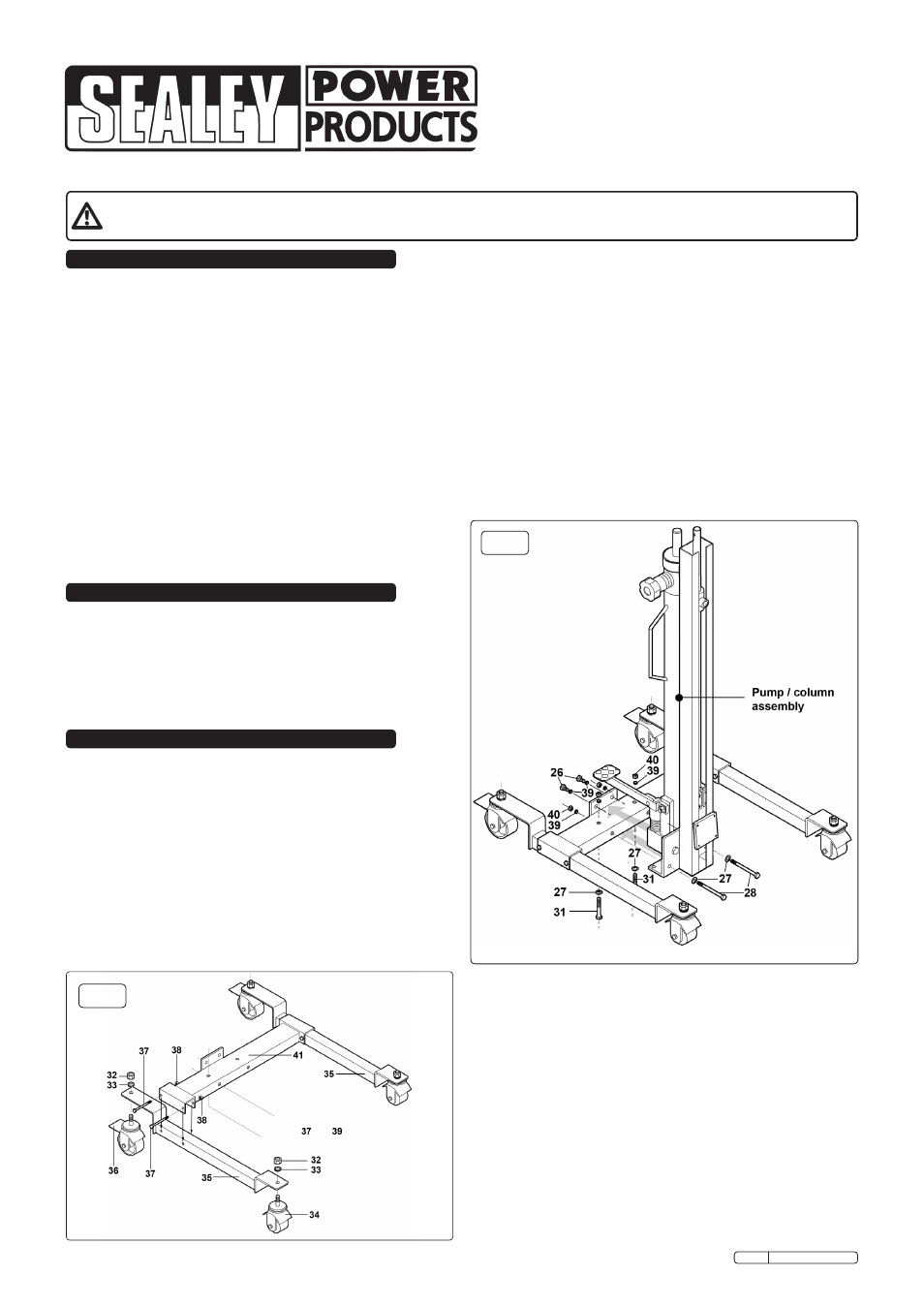
3.2
Assembling the pump/column to the castor base.
3.2.1 the pre-assembled pump and column unit is fixed to the supporting
3.3
Assembling the roller support
.
3.3.1 referring to fig.3, take the roller support assembly and bolt it to the
angled plate at the base of the column using four socket cap bolts (20).
3.3.2 there are two mounting positions for the right hand roller. choose the
position to suit the job in hand.
3.4
Assembling the bridge joint
.
3.4.1 referring to fig.3, take the bridge joint (2) and push it onto the end of
the hydraulic ram so that channel walls lie either side of the lifting rod.
slide the washer (4) onto the bolt (3) and insert the bolt through the
channel and through the lifting rod. secure the bolt with a spring washer
(5) and nut (6).
Insert the thumb screw (1) into the collar of the bridge
joint and tighten it.
3.5
Assembling the slide bar and safety rod
.
3.5.1 referring to fig.3, take the safety rod (13) and insert the slide bar (14)
into and through the collar at the top of the safety rod. Insert the
threaded end of the slide bar into slide tube (10). Move the assembly up
the lifting rod and lock it in the required place by turning the knob at the
end of the slide bar clockwise until it is tight. Insert the butterfly nut (12)
into the safety rod collar. Move the safety rod along the slide bar to the
required position and tighten the butterfly nut.
beam using three pairs of fixings, two pairs in the horizontal plane and
one pair in the vertical plane.
3.2.2 referring to fig.2, take the pre-assembled pump and column unit and
slide it onto the main support beam and up against the vertical plate
welded to the support beam. Align the holes in the pump block with the
holes in the vertical plate. slide a spring washer (39) onto each socket
cap bolt (26) and insert the bolts through the plate and screw them
finger tight into the pump block.
3.2.3 slide a washer (27) onto each long bolt (28) and insert the bolts
horizontally through the column bracket and all the way through the
main support beam. secure the bolts finger tight only at this stage using
using two spring washers (39) and two nuts (40).
3.2.4 slide a washer (27) onto each long bolt (31) and insert the bolts
vertically from underneath, through the corners of the column bracket
and all the way through the main support beam. secure the bolts on the
top surface of the beam using two spring washers (39) and two nuts (40).
3.2.5 now progressively tighten all three pairs of fixings checking that the
pump/column remains vertical.
Original Language Version
WD80 Issue: 2 - 10/11/10
fig.1
fig.2