Sealey VSE952 User Manual
Vse952, Model, Vacuum & fuel pump pressure test gauge
✓
Observe standard workshop safety procedures when using the test gauge.
✓
Wear safety eye protection and protective clothing. Avoid touching eyes while working with petrol.
✓
Have fresh water and soap nearby in case petrol contacts skin, clothing or eyes.
✓
Remove loose personal items such as rings, bracelets, necklaces, ties and contain long hair.
✓
Ensure hands, clothing are clear of fan blades and other moving or hot parts of engine.
✓
Keep the work area clean and uncluttered and ensure there is adequate lighting.
✓
Maintain correct balance and footing. Ensure the floor is not slippery and wear non-slip shoes.
✓
Keep children and unauthorised persons away from the working area.
✓
Ensure that connections for testing the fuel pump are secure and free from leaks.
❐
WARNING! DO NOT use test gauge on any vehicles other than those with carburettor fuel systems.
✗
DO NOT smoke or allow a spark or flame in and around the vehicle.
✗
DO NOT dismantle the test gauge. The test gauge must be checked by qualified service personnel only.
✗
DO NOT get tester wet or use in damp or wet locations or areas where there is condensation.
✗
DO NOT use the tester for any purpose other than that for which it is designed.
✗
DO NOT operate the tester if damaged.
✓
When not in use store tester in a safe, dry, childproof location.
INSTRUCTIONS FOR:
VACUUM & FUEL PUMP PRESSURE
TEST GAUGE
Model:
VSE952
Thank you for purchasing a Sealey product. Manufactured to a high standard this product will, if used according to these instructions and properly maintained, give you years
of trouble free performance.
IMPORTANT! PLEASE READ THESE INSTRUCTIONS CAREFULLY. NOTE THE SAFE OPERATIONAL REQUIREMENTS, WARNINGS AND CAUTIONS.
USE THIS PRODUCT CORRECTLY AND WITH CARE FOR THE PURPOSE FOR WHICH IT IS INTENDED. FAILURE TO DO SO MAY CAUSE DAMAGE, OR
PERSONAL INJURY AND WILL INVALIDATE THE WARRANTY.
1. SAFETY INSTRUCTIONS
2. INTRODUCTION
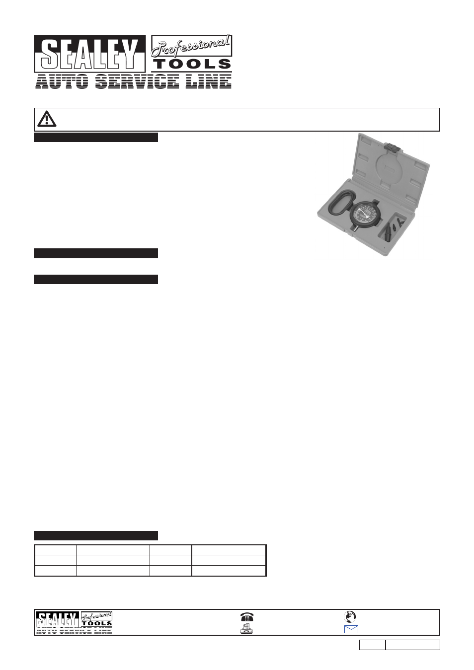
Ø80mm Gauge with protective rubber bumper and hanging hook. Checks for leaks in fuel line, vacuum chokes and heating. Also suitable for diagnosing valve problems. Includes
long flexible hose and adaptors. Supplied in storage case.
3. OPERATION
4. PARTS
NOTE: It is our policy to continually improve products and as such we reserve the right to alter data, specifications and component parts without prior notice.
IMPORTANT: No liability is accepted for incorrect use of product.
WARRANTY: Guarantee is 12 months from purchase date, proof of which will be required for any claim.
INFORMATION: For a copy of our latest catalogue call us on 01284 757525 and leave your full name and address, including postcode.
01284 757500
01284 703534
Sole UK Distributor
Sealey Group,
Bury St. Edmunds, Suffolk.
www.sealey.co.uk
W e b
VSE952
Issue No: 1 - 14/07/08
3.1
VACUUM TEST.
3.1.1
Use the supplied adaptors to connect gauge hose as close to the inlet manifold as possible, ensure that the hose is not kinked. Should an engine have two inlet
manifolds carry out separate tests on each manifold.
3.1.2
Start engine, if required adjust idle speed to obtain a smooth tick over.
3.1.3
If the gauge needle remains steady with a reading between 17 and 22 inHg, the engine is in good condition.
3.1.4
If the gauge drops back about 4 inHg on the dial, this would indicate sticky valves, disconnect the vacuum hose and spray penetration oil into the manifold to
lubricate the valves.
3.1.5
If the needle consistently drops, this would indicate that the valve clearances are too tight or that a valve has burnt out.
3.1.6
If the needle pulsates rapidly when the rpm is increased, this indicates that the valve springs may be weak.
3.1.7
If the needle pulsates rapidly at idle and steadies out when the rpm is increased, indicates that the valve guides are worn or loose.
3.1.8
If the needle is slow to drop back after the engine rpm has been increased several times in succession, would indicate that the exhaust system may be partially
blocked.
3.1.9
If the gauge indicates less than 10 inHg, this would indicate that the valve timing is late.
3.1.10 To check the choke, close the throttle and turn the engine over using the starter motor, the gauge should rise quickly to 22 inHg. If the gauge remains at a
low reading or 3 to 6 inHg then the throttle may not be fully closed or there may be an air leak in the inlet manifold.
Note:
Gauge readings will vary with altitude, at sea level the approximate reading will be 19.5 inHg, for every 1000ft above sea level the vacuum gauge will drop by 1 inHg.
For instance at 2000ft the reading will be 17.5 inHg.
3.2
FUEL PUMP VACUUM TEST. (Mechanical fuel pumps only).
3.2.1
Disconnect the inlet pipe to the fuel pump and plug the hose to avoid spillage.
3.2.2
Connect the vacuum pipe to the inlet connection of the fuel pump.
3.2.3
Start the engine, if the gauge indicates approximately 10 inHg the pump is in good condition.
3.3
FUEL PUMP PRESSURE TEST. (Mechanical fuel pumps only).
3.3.1
Disconnect the fuel pipe from the outlet of the fuel pump.
3.3.2
Connect the gauge hose to the outlet side of the fuel pump.
3.3.3
Start the engine, there should be enough fuel in the carburettor to allow the engine to run for about two minutes.
3.3.4
Check the pressure reading against manufacturers specifications for that model.
3.3.5
The fuel pump pressure should remain fairly constant for several minutes after the engine has stopped. If pressure reduces quickly check the fuel pump diaphragm and
seals for leaks.
3.4
CARBURETTOR TEST.
Note:
Ensure that the spark plugs, ignition timing and valve clearances are all correctly adjusted before adjusting the carburettor.
3.4.1
Connect the gauge hose to the inlet manifold.
3.4.2
Start engine and allow to reach normal operating temperature. At idling speed the gauge should have a steady reading between 17 and 22 inHg, if the needle varies
between 14 and 22 inHg, this indicates that the carburettor requires adjustment.
3.4.3
Adjust the carburettor as follows:
a) At idling speed adjust the mixture screw until the highest reading is obtained and the needle is steady.
b) If a high speed adjustment is required, increase the engine speed to 2000 to 2500rpm and adjust the mixture until the highest reading is obtained with a
steady needle.
c) If the carburettor has a high and low speed setting adjust the high speed setting first.
Note:
If the carburettor is worn, has blocked jets or incorrect jets fitted it may not be possible to adjust the carburettor to its optimum.
VSE952.01
Gauge
VSE952.04
Connector (T-Piece)
VSE952.02
Hose
VSE952.05
Connector (Cone)
VSE952.03
Connector
VSE952.06
Gauge Surround