Sealey VS311 User Manual
Vs311.v2, Glow plug thread repair set 33pc, Instructions for
INSTRUCTIONS FOR:
GLOW PLUG THREAD REPAIR SET 33pc
MODEL No:
VS311.V2
1. SAFETY InSTRUcTIOnS
Thank you for purchasing a Sealey product. Manufactured to a high standard this product will, if used according to these instructions and properly
maintained, give you years of trouble free performance.
IMPORTANT: PLEASE READ THESE InSTRUcTIOnS cAREFULLY. nOTE THE SAFE OPERATIOnAL REQUIREMEnTS,
WARnInGS AnD cAUTIOnS. USE THE PRODUcT cORREcTLY AnD WITH cARE FOR THE PURPOSE FOR WHIcH IT IS
InTEnDED. FAILURE TO DO SO MAY cAUSE DAMAGE AnD/OR PERSOnAL InJURY AnD WILL InVALIDATE THE WARRAnTY.
PLEASE KEEP InSTRUcTIOnS SAFE FOR FUTURE USE.
2. InTRODUcTIOn & SPEcIFIcATIOnS
WARnInG! Ensure Health and Safety, local authority and general workshop practice regulations are adhered to when using tools.
DO nOT use tools if damaged.
DO nOT use this tool for purposes other than for which it is designed.
Maintain tools in good and clean condition for best and safest performance.
Wear approved eye protection. A full range of personal safety equipment is available from your Sealey dealer.
Wear suitable clothing and tie back long hair to avoid snagging.
DO nOT wear jewellery.
Keep children and unauthorised persons away from the work area.
Account for all tools and parts being used and do not leave them in or near the engine.
DO nOT use the thread repair set when you are tired or under the influence of alcohol, drugs or intoxicating medicines.
DO nOT attempt to start engine or move vehicle, whilst tools are fitted and work is in progress.
Ensure any disconnected fuel pipes are plugged to avoid spillage.
Account for all tools and parts being used, return all parts to the case and store this in a safe, dry, childproof location.
DO nOT leave them
in or near the engine
IMPORTANT: These instructions are provided as a guide only. Always refer to the vehicle manufacturer’s service instructions, or a
proprietary manual, to establish the current procedure and data.
WARnInG! Failure to comply with these instructions may result in damage to the thread repair set or vehicle and/or personal injury.
WARnInG! The warnings referred to in this guide cannot cover all possible conditions and situations that may occur. It must be understood
that common sense and caution are factors which cannot be built into this product, but must be applied by the operator.
Fast and effective remedy for damage to cylinder head glow plug threads. Set includes tools for the precise insertion of threaded inserts into the
head and features a unique tap guide system to ensure their correct alignment. Includes 4 sizes of threaded adaptors suitable for common sizes
of glow plug. Supplied in storage case.
Specifications:
Model No: . . . . . . . . . . . . . . . . . . . . . . . . . . . . . . . . . . . . . . . . . . . . . . . . . . . . . . . . . . . . . . . . . . . . . . . . . . . . . . . . . . . . . . . . . . . . . . . . . .VS311.V2
Tap: . . . . . . . . . . . . . . . . . . . . . . . . . . . . . . . . . . . . . . . . . . . . . . . . . . . . . . . . . . . . . . M14x1.25, M12x1.25, M12x1.0, M10x1.25, M10x1.0, M8x1.0
Inserts: . . . . . . . . . . . . . . . . . . . . . . . . . . . . . . . . . . . . . . . . . . . . . . . . . . . . . . . . . . . . . . . . . . . . . . . . . . . . . M12x1.25, M10x1.25, M10x1.0, M8x1.0
Replacement Inserts (Packs of 5): . . . . . . . . . . . . . . . . . VS311.01 (M8x1.0), VS311.02 (M10x1.0), VS311.03 (M10x1.25), VS311.04 (M12x1.25)
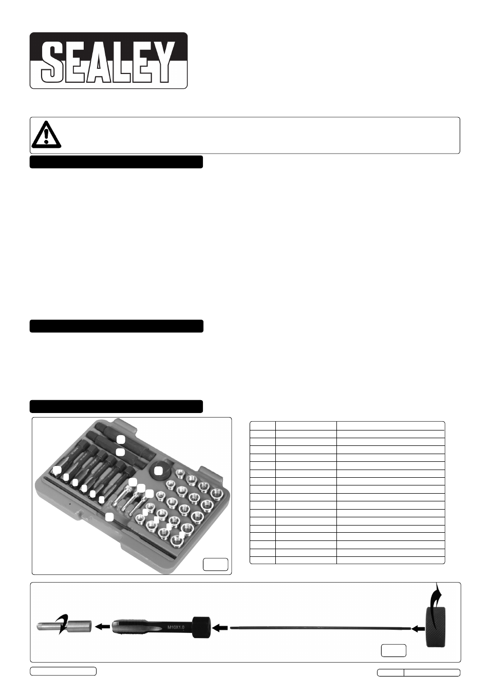
3. cOnTEnTS
fig.1
14
15
16
17
12
1
2
13
9
10
11
3
4
5
6
7
8
VS311.V2 Issue No: 1 - 04/11/13
Original Language Version
© Jack Sealey Limited
Item No: Part No:
Description:
1
VS311.01
Thread Insert M8 x 1.0
2
VS311.02
Thread Insert M10 x 1.0
3
VS311.03
Thread Insert M10 x 1.25
4
VS311.04
Thread Insert M12 x 1.25
5
VS311.05
Tap M8 x 1.0
6
VS311.06
Tap M10 x 1.0
7
VS311.07
Tap M10 x 1.25
8
VS311.08
Tap M12 x 1.0
9
VS311.09
Tap M12 x 1.25
10
VS311.10
Tap M14 x 1.25
11
VS311.11
Insert Driver M8x1.0 & M10x1.0
12
VS311.12
Insert Driver M10x1.25 & M12x1.25
13
VS311.V2.13
Tap Guide Pin ø8 x 45
14
VS311.V2.14
Tap Guide Pin ø10 x 45
15
VS311.V2.15
Tap Guide Pin ø12 x 45
16
VS311.16
Insert Guide Rod
17
VS311.17
Knurled Head
fig.2