Sealey GA42 User Manual
Model no: ga42.v2, Camber, castor & king pin gauge set, Instructions for
INSTRUCTIONS for:
CAMBER, CASTOR & KING PIN
GAUGE SET
MODEL No: GA42.V2
Thank you for purchasing a Sealey product. Manufactured to a high standard this product will, if used according to these instructions
and properly maintained, give you years of trouble free performance.
1. SAFETY INSTRUCTIONS
IMPORTANT: PLEASE READ THESE INSTRUCTIONS CAREFULLY. NOTE THE SAFE OPERATIONAL REQUIREMENTS, WARNINGS & CAUTIONS.
USE THE PRODUCT CORRECTLY AND WITH CARE FOR THE PURPOSE FOR WHICH IT IS INTENDED. FAILURE TO DO SO MAY CAUSE
DAMAGE OR PERSONAL INJURY, AND WILL INVALIDATE THE WARRANTY. PLEASE KEEP INSTRUCTIONS SAFE FOR FUTURE USE.
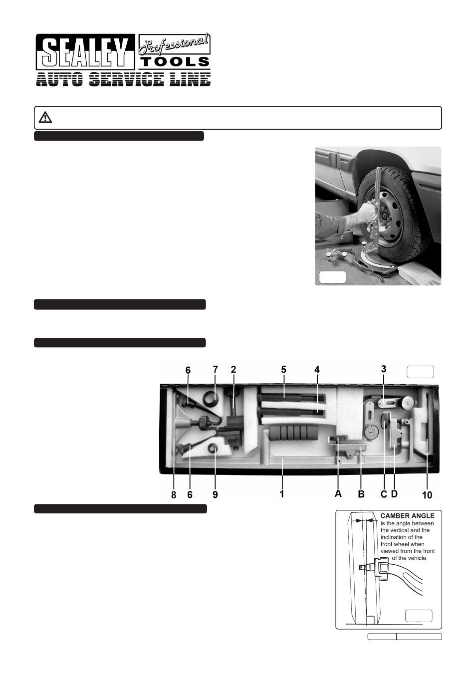
3. CONTENTS
2. INTRODUCTION & SPECIFICATION
WARNING! Ensure Health & Safety, local authority, and general workshop practice
regulations are adhered to when using this equipment.
Maintain the set in good condition (use an authorised service agent).
Replace or repair damaged parts. Use genuine parts only. Non-authorised parts may be
dangerous and will invalidate the warranty.
WARNING! Use this set on vehicles that are parked on level and solid ground.
Locate vehicle in a suitable working area, keep area clean and tidy and free from unrelated
materials.
DO NOT use outside in damp or wet weather conditions.
DO NOT allow untrained persons to use this set.
Keep the set clean to ensure accurate performance.
WARNING! When setting front end alignment on commercial vehicles, never make
adjustments to drop arms or interconnecting links. Doing so could result in serious tyre,
wheel and steering problems.
NOTE: Any alignment changes deemed necessary as a result of using this equipment
must be made strictly in accordance with the vehicle manufacturer’s recommendations.
WARNING! The warnings, cautions and instructions contained within this document cannot
cover all possible conditions and situations that may occur. It must be understood that
common sense and caution are factors which cannot be built into this product, but must be
applied by the operator.
This set consists of two separate instruments. The long handled assembly is used to measure camber angles and check floor level. The
smaller assembly checks castor angles and king pin inclination in one operation and can be attached to a stub axle nut, to a wheel stud or to
a centre lock wheel. It is recommended that these instruments are used in conjunction with our GA44 steering turntables for greater accuracy.
Carefully unpack the contents of the box. If any parts are missing or damaged, contact your Sealey dealer immediately.
Contents:
1.
Camber Angle Gauge.
2.
Stud Axle Clamp.
3.
Castor and King Pin Gauge.
4.
Wheel Stud Mounting Bracket -
Large (for use with item 3).
5.
Wheel Stud Mounting Bracket -
Small (for use with item 3).
6.
Hooks for Centre Lock Clamp.
7.
Large Conical Washer (for use
with item 4).
8.
Centre Lock Clamp.
9.
Small Conical Washer (for use
with item 5).
10.
Pin (for tightening item 2).
fig.2
fig.1
4. MEASURING CAMBER ANGLE
4.1.
Check that the floor is level as described in Section 6, and that the tyre pressures are correct.
4.2.
To set the gauge up, hold it in the vertical position and adjust the ‘camber’ dial (fig.2.C) so that
‘0’ is in line with the index mark.
4.3.
Apply the long edge of the gauge to the tyre side wall holding it in a vertical position (fig.1). To
obtain an accurate reading, avoid the part of the tyre wall that bulges near ground level.
4.4.
Turn the camber dial (fig.2.C) in either direction until the bubble in the spirit level (fig.2.D) is
centred. The number of graduations turned through, represents the camber ‘in’ or camber ‘out’
in degrees depending on which direction it was necessary to turn the dial.
NOTE : If the dial is rotated more than half a revolution (3 graduations) and the spirit level
bubble has not centred, continue to turn the dial until the bubble has centred and make a note of
the graduations needed (i.e. they will not be correctly numbered after 3 graduations).
4.5.
If it has been established that the floor is not level, make any necessary adjustments to the
readings (See Section 6 chart).
4.6.
Any changes deemed necessary as a result of using this set, must be made strictly in
accordance with the vehicle manufacturer’s recommendations.
fig.3
Original Language Version
GA42.V2 Issue: 1 - 29/07/10