Sealey VS1270 User Manual
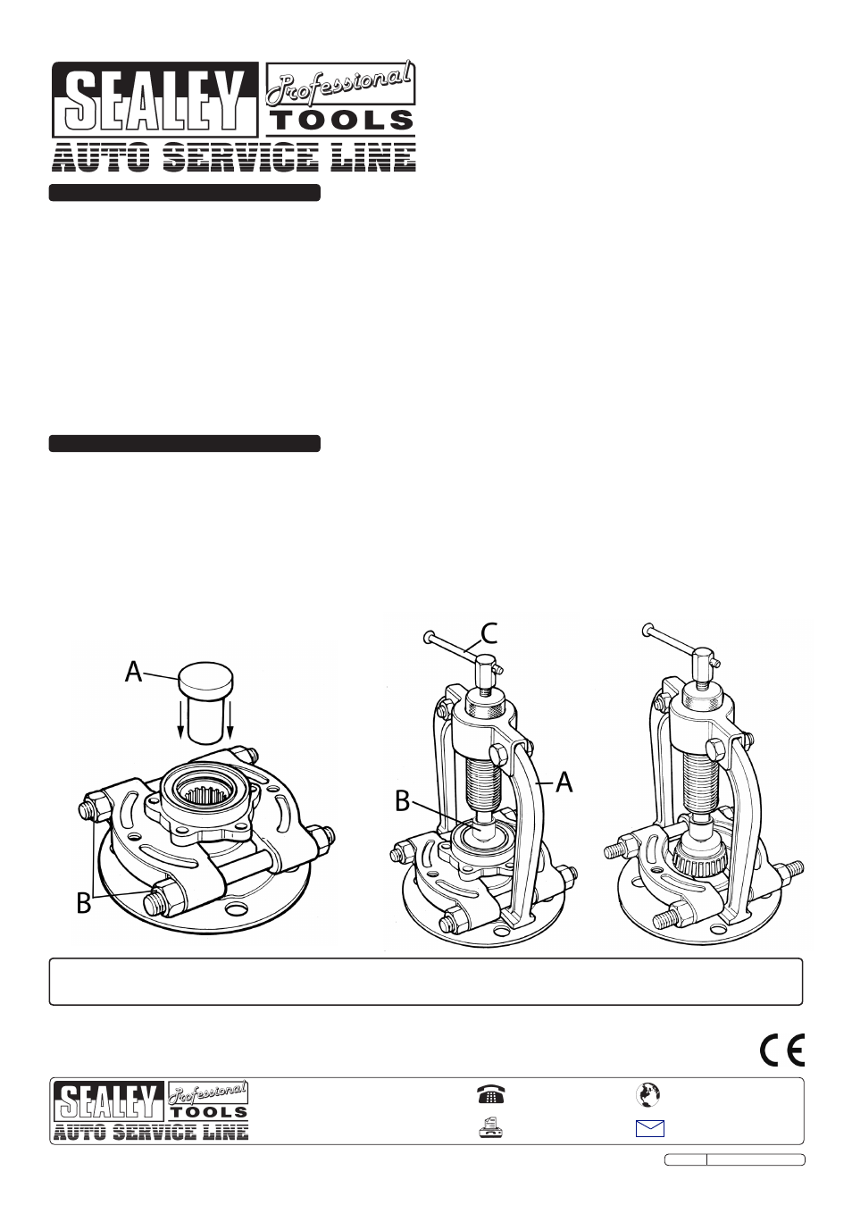
Fig.1 fig.2 fig.3
WARNING! Ensure all Health and Safety, local authority, and general workshop practice regulations are strictly adhered to
when using tools.
DO NOT use tools if damaged or worn.
Maintain the tools in good and clean condition for best and safest performance.
Ensure all threads are clean and well lubricated.
Ensure vehicle is adequately supported with axle stands, ramps, etc. as appropriate.
Wear suitable clothing to avoid snagging. Do not wear jewellery. Tie back long hair.
Wear approved eye protection. A full range of personal safety equipment is available from your Sealey dealer.
Account for all tools and parts being used and do not leave them in or on the vehicle.
IMPORTANT: Always refer to the vehicle manufacturer’s service instructions, or proprietary manual, to establish the correct
procedure and data. These instructions for use are provided as a guide only.
WARNING: The warnings,and instructions discussed in this instruction manual cannot cover all possible conditions and
situations that may occur. It must be understood that common sense and caution are factors which cannot be built into this
product, but must be applied by the operator.
INSTRUCTIONS FOR:
FRONT WHEEL BEARING TOOL
FORD TRANsIT
MODEL NO:
Vs1270
1. sAFETY
2. INsTRucTIONs
fig.1
fig.2
fig.3
2.1 Remove the wheel hub (refer to the manufacturers instructions).
2.2 Place the bearing separator under the bearing assembly, making sure the flat side is facing up and under the bolt holes.
Tighten the bearing separator by turning the nuts evenly (fig.1B).
2.3 Place the puller insert into the centre of the hub, see fig.1A.
2.4 Slide the tools arms (fig.2A) under the separator, attach ram adapter (fig.2B), if needed, attach the ram extension (not shown)
and make sure that the ram is central on the puller insert.
2.5 Turn the T-bar (fig.2C) clockwise to apply pressure to remove the bearing. If the T-bar has been wound in and the bearing
has not been released wind out the T-bar and lower the ram to make up for the slack, repeat this process until the bearing is
removed.
2.6 To remove the inner part of the bearing, remove the separator and turn it upside down, replace onto the hub and tighten the
nuts (fig.3), repeat the above process from 2.4.
Original Language Version
VS1270 Issue No.2 16/05/11
NOTE: It is our policy to continually improve products and as such we reserve the right to alter data, specifications and component parts without prior notice.
IMPORTANT: No liability is accepted for incorrect use of this product.
WARRANTY: Guarantee is 12 months from purchase date, proof of which will be required for any claim.
INFORMATION: For a copy of our latest catalogue and promotions call us on 01284 757525 and leave your full name and address, including postcode.
sole uK Distributor, sealey Group,
Kempson Way, Suffolk Business Park
,
Bury St. Edmunds, Suffolk,
IP32 7AR
01284 757500
01284 703534
www.sealey.co.uk
Web
Parts support is available for this product. To obtain a parts listing and/or diagram, please log on to
www.sealey.co.uk, email [email protected] or phone 01284 757500.