Sealey VSE4783 User Manual
Vse4783, Front suspension bush tool - bmw mini, Instruction manual for
INSTRUCTION MANUAL FOR:
Front Suspension Bush Tool -
BMW MINI
Model No:
VSE4783
1.
SAFETY INSTRUCTIONS
2.
INTRODUCTION & APPLICATIONS
Thank you for purchasing a Sealey product. Manufactured to a high standard this product will, if used according to these instructions and properly maintained, give
you years of trouble free performance.
IMPORTANT: READ THESE INSTRUCTIONS CAREFULLY. NOTE THE SAFE OPERATIONAL REQUIREMENTS, WARNINGS AND CAUTIONS.
USE THE TOOL CORRECTLY AND WITH CARE FOR THE PURPOSE FOR WHICH IT IS INTENDED. FAILURE TO DO SO MAY CAUSE DAMAGE
AND/OR PERSONAL INJURY AND WILL INVALIDATE THE WARRANTY. PLEASE KEEP INSTRUCTIONS SAFE FOR FUTURE USE.
WARNING! Ensure Health and Safety, local authority and general
workshop practice regulations are adhered to when using tools.
DO NOT use tools if damaged.
DO NOT use puller for purposes other than for which it is
designed.
DO NOT use puller when you are tired or under the influence of
alcohol, drugs or intoxicating medicines.
Maintain tools in good and clean condition for best and safest
performance.
Ensure that a vehicle which has been jacked up is adequately
supported with axle stands and that the wheels are chocked,
refer to the vehicle manufacturer’s service instructions, or a
proprietary manual.
Ensure that work area has adequate lighting.
Keep children and unauthorised persons away from the work
area.
Wear approved eye protection. A full range of personal safety
equipment is available from your Sealey dealer.
Wear suitable clothing to avoid snagging. Do not wear jewellery
and tie back long hair.
DO NOT use air tools to operate the force screw.
When not in use, store puller in a safe, dry childproof area.
IMPORTANT: The force screw must be kept well lubricated.
IMPORTANT: This manual is provided as a guide only, refer to
the vehicle manufacturer’s service instructions, or a proprietary
manual, to establish the current procedure and data.
WARNING! Failure to comply with these instructions may
result in damage to the puller or vehicle and/or personal injury.
WARNING ! The warnings, cautions and instructions
referred to in this manual cannot cover all possible
conditions and situations that may occur. It must be
understood that common sense and caution are factors
which cannot be built into this product, but must be applied
by the operator.
Suitable for the removal/installation of the front control arm suspension
bush on BMW Mini. Supplied with instructions in carry-case.
Applications:
One, Cooper, Cooper S (2001 on) R50/R53 Chassis W10/W11/
•
W17.
Bush OE Number: 31 12 6 757 551
•
3.
OPERATION
NOTE! Pictures taken with the front control arm removed from
vehicle for clarity. Refer to the vehicle manufacturer’s service
instructions, or a proprietary manual to carry this out.
NOTE! These bushes can be secured into the housing with a
bonding compound and may be very tough to remove. Maximum
torque on the force screw is 150Nm. If greater force is required
the bush should be removed with the supplied adaptors using a
suitable press.
NOTE! This tool will insert the bush to the correct depth, but
before installing the new bush, refer to the vehicle
manufacturer’s service instructions, or a proprietary manual, to
establish the correct horizontal alignment/positioning of the bush.
IMPORTANT: This tool is designed to aid removal of the bush.
We suggest that the area around the bush is thoroughly cleaned.
•
The threads of the tool should also be thoroughly lubricated in use.
•
An Impact Wrench must NOT be used with this tool.
•
Stripped threads and bent thrust cups are not accepted
•
warranty claims on this tool.
3.1. Removing bush.
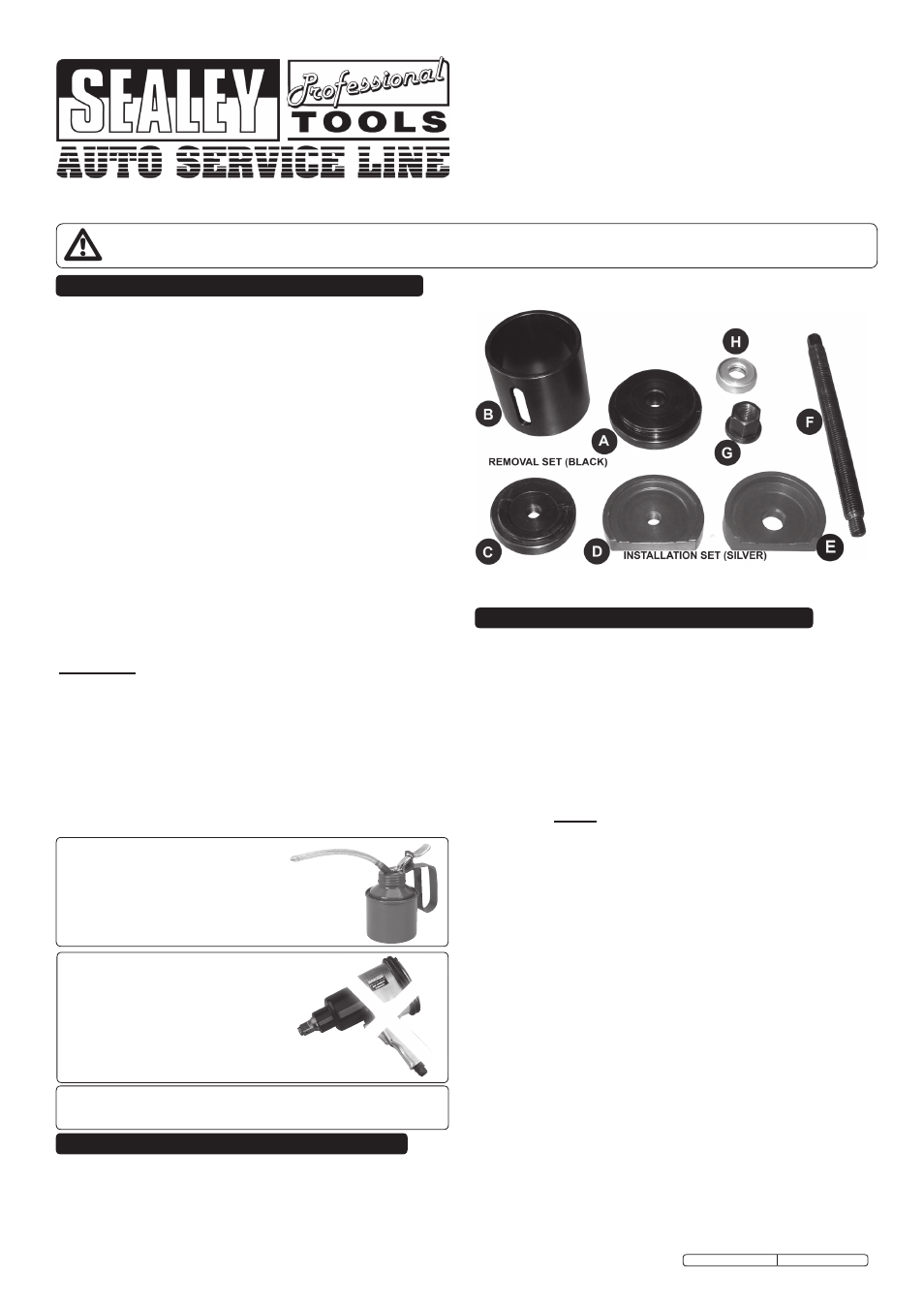
3.1.1. Assemble the removal (black) set as in fig.1. Thread the adaptor
(C) onto the short threaded end of the force screw (F) with the
ridged side of adaptor (C) facing inwards. Pass the force screw
(F) through the bush from the rear and position adaptor (C) so
that the ridge sits in the recessed area of the bush (fig.2).
Position adaptor (B) over the force screw (F), then fit adaptor (A)
so that the seal sits inside adaptor (B). Fit the bearing (H) and
then thread the nut (G) onto the force screw (F) and wind it up to
the adaptor (A). Double check to make sure that everything is
aligned.
3.1.2. Using a 24mm deep socket or spanner, turn the nut (G)
clockwise. The extractor will start to extract the bush through
the front control arm housing.
DO NOT apply more than 150Nm
of torque.
3.1.3. Keep turning until the bush has been extracted all the way out
of the front control arm. Take care as the bush and assembly will
fall away when the bush is fully removed.
NOTE! If any undue resistance is felt, remove the assembly and
check everything is correctly aligned.
ALWAYS KEEP FORCE SCREW
WELL LUBRICATED.
DO NOT USE AIR TOOLS
Original Language Version
VSE4783 Issue: 2 - 23/08/11
Force screw maximum load 150Nm. Exceeding this load will
shorten the life of the force screw. The force screw is considered
to be a consumable item and is NOT covered under warranty.