Sealey MIG/N315 User Manual
Mig torch euro connector, Fig.1 fig.2
INSTRUCTIONS FOR:
MIG TORCH EURO CONNECTOR
PART Nos
:
MIG/N315, MIG/N325, MIG/N336,
MIG/N415, MIG/N425, MIG/N436
Thank you for purchasing a Sealey Product. Manufactured to a high standard this product will, if used according to these instructions and properly maintained, give you
years of trouble performance.
IMPORTANT: PLEASE READ THESE INSTRUCTIONS CAREFULLY. NOTE THE SAFE OPERATIONAL REQUIREMENTS, WARNINGS AND CAUTIONS.
USE THIS PRODUCT CORRECTLY AND WITH CARE FOR THE PURPOSE FOR WHICH IT IS INTENDED. FAILURE TO DO SO MAY CAUSE DAMAGE
AND/OR PERSONAL INJURY AND WILL INVALIDATE THE WARRANTY. PLEASE KEEP INSTRUCTIONS SAFE FOR FUTURE USE.
1.
SAFETY INSTRUCTIONS
2.
INTRODUCTION & SPECIFICATIONS
3.
TIP & SHROUD REMOVAL
■
BEFORE USE, ALWAYS ENSURE THAT YOU ARE FAMILIAR WITH THE SAFETY WARNINGS AND INSTRUCTIONS FOR THE
WELDER TO WHICH THIS TORCH IS TO BE FITTED.
DO NOT exceed the rated current of the torch.
DO NOT use if any part of the torch, cable or connector is damaged in any way. Use only genuine Sealey replacement parts to effect
repairs.
DO NOT allow the cable to come into contact with any sharp or hot items.
Always use the correct personal protective equipment as specified in the welder instructions.
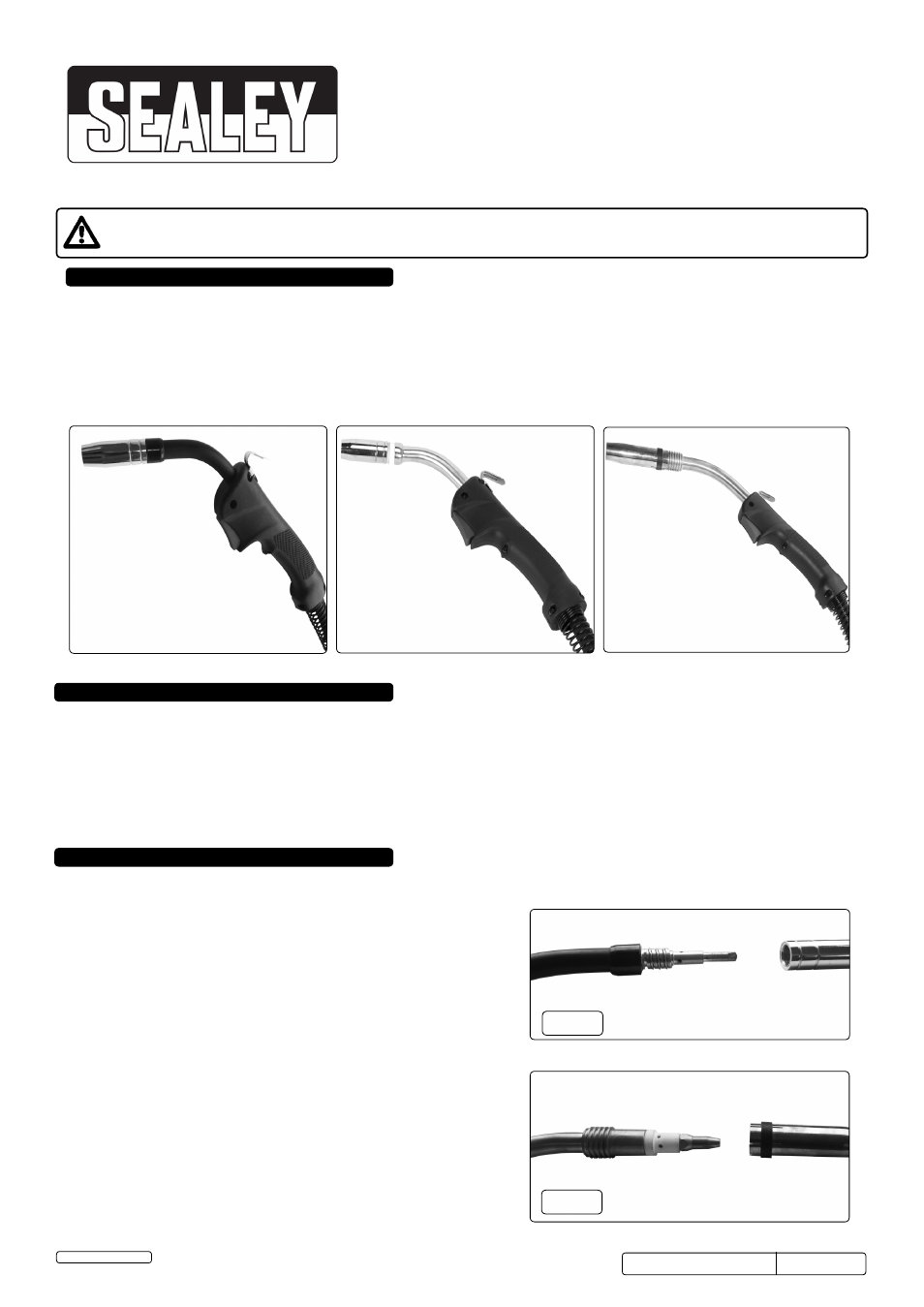
MIG/N315, MIG/N415
MIG/N336, MIG/N436
Professional MIG welding torches with contoured grip, hanging hook and heat-proof cable. Fitted with Euro connection enabling a quick and simple
plug connection to welder. No wiring means torch can be disconnected and stored safely when not being used.
Model No: . . . . . . .MIG/N315. . . . . . . .MIG/N325. . . . . . . . MIG/N336. . . . . . . MIG/N415 . . . . . . MIG/N425 . . . . . . . MIG/N436
Rated Current: . . . .180A. . . . . . . . . . . .230A. . . . . . . . . . . . 250A. . . . . . . . . . . 290A. . . . . . . . . . . 340A . . . . . . . . . . . .350A
Wire Diameter:. . . .0.6-1mm . . . . . . . . .0.8-1.2mm . . . . . . . 0.8-1.2mm . . . . . . 0.8-1.2mm . . . . . . 0.8-1.6mm. . . . . . . .1-2.4mm
Length:. . . . . . . . . .3mtr . . . . . . . . . . . .3mtr . . . . . . . . . . . . 3mtr . . . . . . . . . . . 4mtr . . . . . . . . . . . 4mtr. . . . . . . . . . . . .4mtr
Torch Type: . . . . . .MB15 . . . . . . . . . . .MB25 . . . . . . . . . . . MB36 . . . . . . . . . . MB15 . . . . . . . . . . MB25 . . . . . . . . . . .MB36
MIG/N325, MIG/N425
ENSURE THAT THE TORCH IS COOL AND THAT THE WELDER IS DISCONNECTED FROM THE POWER SUPPLY.
3.1.
MIG/N315, MIG/N415, MIG/N325, MIG/N425 (fig.1)
3.1.1. To remove the shroud: turn the shroud clockwise and pull away.
3.1.2. To remove the tip: unscrew the tip in an anticlockwise direction.
3.1.3. To replace the tip: screw back in and tighten.
3.1.4. To replace the shroud: simply push the shroud back over the spring.
3.2.
MIG/N336, MIG436 (fig.2)
3.2.1. To remove the shroud: pull the shroud forward to release.
3.2.2. To remove the tip: unscrew the tip in an anticlockwise direction.
3.2.3. To replace the tip: screw back in and tighten.
3.2.4. To replace the shroud: push back over the torch head.
fig.1
fig.2
Original Language Version
MIG/N315,MIG/N325,MIG/N336, Issue: 1- 28/02/14
MIG/N415,MIG/N425,MIG/N436
Jack Sealey Limited