Sealey TBB230 User Manual
Page 2
5 . ASSEMBLY
TBB230 Issue no.1 17/11/11
Original Language Version
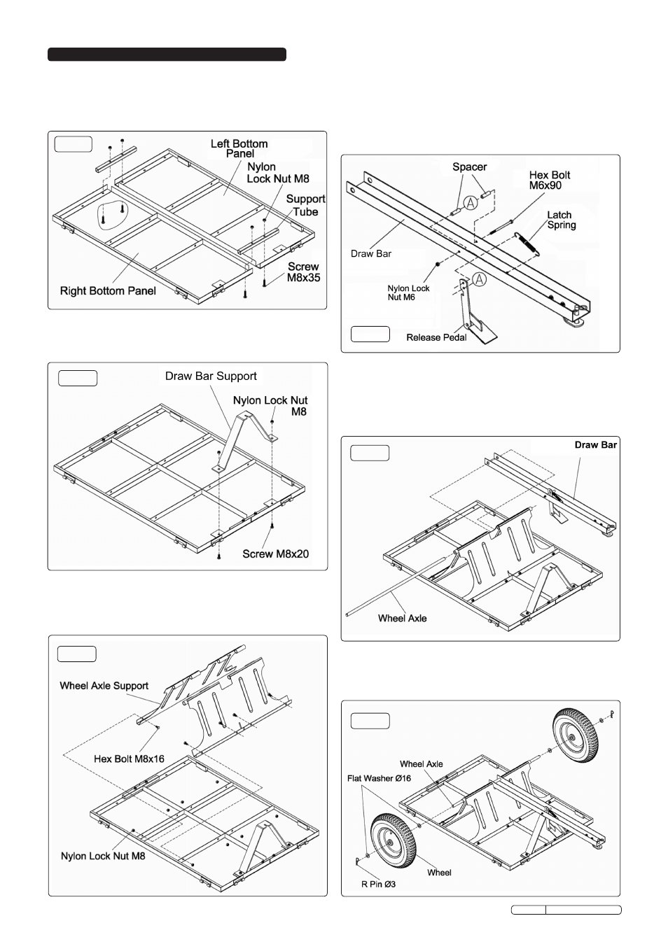
fig.1
fig.2
fig.3
fig.4
fig.5
fig.6
5.1. Attach the Bottom Panels and Support Tubes.
5.1.1 Lay the left and right bottom panels together as shown in fig.1.
5.1.2 Join the panels together with the two support tubes using four
sets of M8x35mm screws and M8 nylock lock nuts. Hand
tighten the nuts.
5.4 Attach the release pedal.
5.4.1 Insert the release pedal through the slot in the draw bar and
create the pedal pivot by inserting an M6x90mm hex bolt
through the draw bar and hole 'A' in the pedal. Two spacer
tubes should also be placed on the bolt, one either side of the
pedal to keep it centrally placed within the draw bar. Retain the
assembly with an M6 nylon lock nut.
5.4.2 Attach the latch spring between the hole in the pedal lever and
the hole in the draw bar as indicated in fig.4.
5.2. Attach the Draw Bar Support.
5.2.1 Attach the draw bar support to the bottom panels using two
M8x20mm screws and M8 nylon lock nuts. Hand tighten the nuts.
5.3 Attach the Wheel Axle Supports.
5.3.1 Connect the two wheel axle supports and attach them to the
bottom panels using eight sets of M8x16 hex bolts and M8
nylon lock nuts. Hand tighten the nuts.
5.5 Attach the wheel axle.
5.5.1 Insert the draw bar assembly into the central slot in the wheel
axle support.
5.5.2 Insert the axle through the hole and slide it through both the
axle support and the draw bar assembly.
5.5.3 Tighten all fixings, previously left hand tight.
5.6 Attach the wheels.
5.6.1 Put a Ø16mm washer over the end of each axle followed by a
wheel and then another Ø16mm washer.
5.6.2 Secure each wheel with an Ø3mm 'R' pin as shown in fig.6.