Fig.2 fig.3 fig.1 – Sealey LP370 User Manual
Page 2
Model No: . . . . . . . . . . . . . . . . . . . . . . . . . . . . . . . . . . . . . . . . . . . . . . . . . . . . . . . LP370
Output (kW): . . . . . . . . . . . . . . . . . . . . . . . . . . . . . . . . . . . . . . . . . . . . . . . . . . . . . 48-108
Output (Btu/hr): . . . . . . . . . . . . . . . . . . . . . . . . . . . . . . . . . . . . . . . . . 166,546-370,934
Airflow (cfm): . . . . . . . . . . . . . . . . . . . . . . . . . . . . . . . . . . . . . . . . . . . . . . . . . . . . . .2178
Fuel Consumption (kg/hr): . . . . . . . . . . . . . . . . . . . . . . . . . . . . . . . . . . . . . 3.094-6.899
Electrical Input (V):. . . . . . . . . . . . . . . . . . . . . . . . . . . . . . . . . . . . . . . . . . . . . . 110/230
Length x Width x Height (mm):. . . . . . . . . . . . . . . . . . . . . . . . . . . . . . .835 x 438 x 606
Fuel:. . . . . . . . . . . . . . . . . . . . . . . . . . . . . . . . . . . . . . . . . . . . . . . . . . . . . . . . . . . Propane
Heated Volume (ft
3
): . . . . . . . . . . . . . . . . . . . . . . . . . . . . . . . . . . . . . . . . . . . . . . . 82,725
Heated Volume (mtr
3)
: . . . . . . . . . . . . . . . . . . . . . . . . . . . . . . . . . . . . . . . . . . . . . . 2,343
Weight (kg):. . . . . . . . . . . . . . . . . . . . . . . . . . . . . . . . . . . . . . . . . . . . . . . . . . . . . . . . . .26
These propane heaters are fan assisted, fitted with a piezoelectric ignition system for trouble-free starting, and feature a direct gas head assembly.
They feature a safety solenoid preventing the unit from leaking gas without first being electrically started. Supplied with an approved propane gas
regulator and hose. All models are tested and certified to CE/EN standards by DVGW. Manufactured to BS EN 416.
LP370 Issue No: 2(I) - 24/09/14
Original Language Version
© Jack Sealey Limited
2. INTRODUCTION
3. SPECIFICATION
4. ASSEMBLY
5. INSTALLATION
Note: Fixings for assembly are located in the heater body.
Refer to attached parts diagram.
4.1.
Fit frame support (back) (21) to body.
4.2.
Pass axle (19) through frame supports (back) (21) and fit wheels (17), washers (16) and wheel covers (15).
4.3. Fit frame supports (front) (22) to both sides of the body.
4.4.
Fit handle supports (4) to both sides of body.
4.5.
Fit handle (5) in between handle supports.
Note: If a small gas cylinder is used, the heater may not operate at maximum efficiency. It is recommended to use two or more cylinders
linked in parallel, to achieve maximum continuous efficiency (fig.2).
5.1.
Setting heater supply voltage.
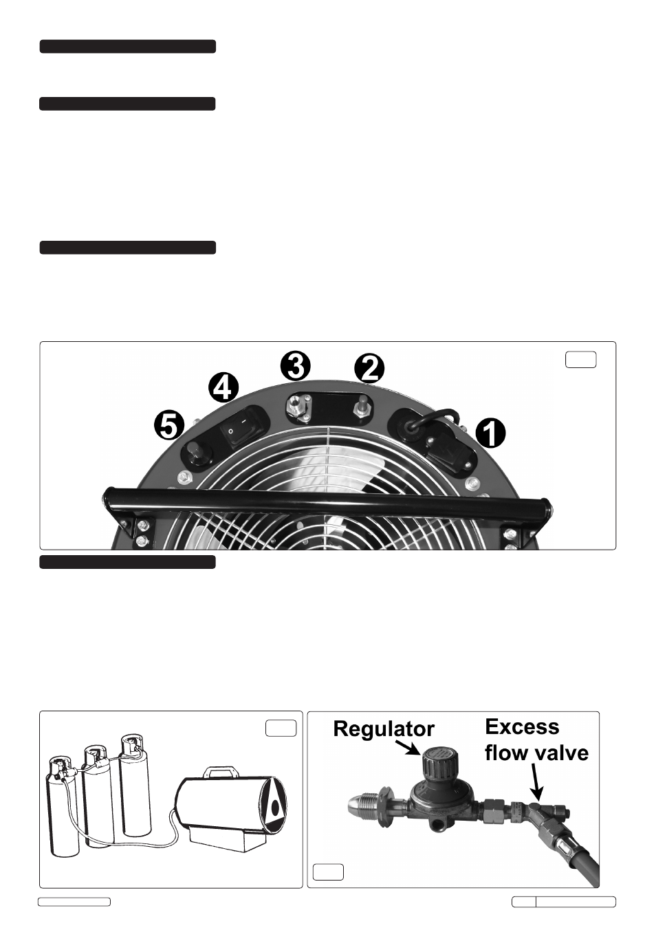
5.1.1. Locate the voltage selection switch (fig.1.1).
5.1.2. If the correct supply voltage is not selected, remove the cover, select the required voltage position and refit the cover panel.
5.2. Connections.
5.2.1. Check heater and gas cylinder to ensure that they are both in good condition. If not, stop and contact your supplier immediately.
5.2.2. Site the heater and gas cylinder in the location to be heated.
5.2.3. Connect the heater to an electrical supply outlet, ensuring that the machine is correctly earthed. See Section 1 Safety Instructions.
5.2.4. Connect the gas supply hose to the excess flow valve (fig.3), connect the valve to the pressure regulator, and connect the regulator to the
gas cylinder.
Note: Left hand threads. Connect the other end of the supply hose to the heater (fig.1.3). Ensure all connections are tight.
5.2.5. Gradually open the tap of the gas cylinder. Check hose and all fittings for any gas leaks.
WARNING! DO NOT USE A NAKED FLAME! To check for leaks, the use of a foamy soap solution is recommended.
fig.2
fig.3
fig.1