Operating conditions, Operating instructions – Sealey AB1008 User Manual
Page 3
4.1
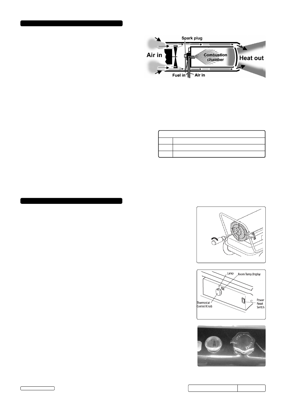
Principles of heat generation
When the heater is switched on the air compressor draws in
air, pressurises it and passes it through an air line to the
burner head nozzle. the air flow causes fuel to be drawn from
the tank. the fuel and air mix is then sprayed into the
combustion chamber. the mixture is automatically ignited by
the spark plug and a high temperature heat stream is
generated in the combustion chamber. Air is drawn into the
unit by a fan and is pushed around the cool chamber situated
between combustion chamber and outer casing. this fast
flowing air sucks the heat stream out of the combustion
chamber, providing the required heat. the heat output is
governed by the compressor - the higher the air pressure the hotter the flame.
If the system malfunctions a “flame-out” control will operate and automatically cut off the motor and fuel supply. should this happen,
switch off machine and unplug from mains supply. refer to trouble shooting chart in section 8 and/or return unit to supplier for
maintenance.
4.2 Fuel
the AB series will operate with three types of fuel, paraffin, kerosene or diesel. the following information must be understood before
use.
4.2.1
Paraffin / Kerosene will sometimes cause condensation. If the unit is stored unused (i.e. during the summer) such condensation will
cause the fuel tank to corrode and, when next used, the flame to pulsate due to water in the tank. to overcome the problem, the fuel
must be drained off, if the heater is to be unused for long periods.
4.3
When used in the construction or agricultural industries ensure that
the safety regulations in force are adhered to with regard to distances
from flammable materials and any other specified substances.
WARNING! Air contaminants taken into the heater may affect the
heat output, damage the unit and may cause health problems.
Example: Bodyshop filler dust or paint overspray will damage the
motor bearing, clog the filter and compressor and contaminate
the combustion chamber causing flame flutter and health hazards.
Please note that any parts damaged by filler dust or overspray will not be covered by warranty.
4.4
VENTILATION. Minimum recommended opening for fresh air intake, AB1008 / AB1008SS = 0.29m², AB1258 = 0.37m²,
AB1758 / AB1758SS = 0.52m² and AB2158 = 0.63m².
WARNING! only use the heater in well ventilated areas. careful consideration must be given to the placing of the heater to provide
safe and comfortable heating. Ensure continuous ventilation is provided to the heater operating area, allow at least 0.01m
2
/kW heater
output. A ventilation opening must run to the outside of the premises in which the heater is to be operated.
4. OPERATING CONdITIONS
fig.2
5. OPERATING INSTRUCTIONS
fig.3 Pump Pressure Adjustment
fig.4 Control Panel
fig.5 Fuel Gauge and Filler
5.1
Running the heater on paraffin / kerosene
the heater has been pre-set at the factory to a setting which is suitable for paraffin,
kerosene or diesel and will produce the correct heat output when first used from new. You
should run the heater at the pre-set output in order to ensure the long life, safety and
reliability of the unit.
WARNING! the first time the heater is used, fire up outdoors and run for at least 10 minutes
to burn off any oils used in the manufacturing process.
5.1.1 Ensure that the unit is unplugged from the mains supply.
5.1.2 fill the fuel tank (fig.5) with paraffin, kerosene or diesel until the fuel gauge points to "f".
dO NOT mix the fuels, always drain and clean out the fuel tank when changing type of fuel.
WARNING! never refill the fuel tank indoors, always refill outside. dO NOT over-fill. Wipe
away any spillage before use.
5.1.3 Plug into the main power supply using the 2m extension cable.
5.1.4 turn the thermostat control knob (fig.4) to the desired temperature setting. the heater has a
range from 4
o
c to 43
o
c. Press the power switch to the "on"(I)position. the lamp and the
room temperature display will illuminate and the heater will start.
NOTE: the electrical components of this heater are protected by a fuse mounted on the PcB. If the
heater fails to fire, check this fuse first and replace if necessary. Also check the power
source to ensure that the proper voltage is being provided to the heater.
NOTE: the room temperature will display will indicate the following:
If the temperature is less than 0°c, the display will show "Lo".
If the temperature is above 37°c,
the display will show "HI"
Actual temperatures will be shown between 4°c and 37°c.
5.1.5 the pump pressure should be +/- 10% of the pressure stated in the specification table
above, if the unit is running outside of this tolerance, adjust the pressure as shown in fig.3.
5.2
shut down the heater using the on/off switch and then disconnect from the mains supply.
5.3
Restarting the heater.
5.3.1 Wait 10 seconds after turning the heater "off" (o).
5.3.2 turn the Power switch to "on" (I).
WARNING! Ensure that all pre-starting precautions are carried out.
5.4
Monitoring the heat output
5.4.1 If, after a period of time, the heat output begins to fall this indicates that either the unit
requires maintenance, as laid out in section 6, or that the environmental conditions the unit
is operating in are not correct, see section 4.
dO NOT ATTEMPT TO TURN UP THE AIR PRESSURE TO COMPENSATE FOR HEAT
LOSS as this could result in damage to the combustion chamber and will invalidate the
warranty.
Minimum Clearances from Combustibles
top
1.2m
sides
1.2m
front
2.4m
AB1008.V2, AB1008ss, AB1258.V2,
AB1758.V2, AB1758ss, AB2158.V2
Issue:4 (I)- 12/09/13
Original Language Version
© Jack sealey Limited