Fig.2 fig.4 fig.3, Assembly 5. operation – Sealey IR37 User Manual
Page 3
5.1. Principles of Operation
5.1.1.
Fuel System: This heater is equipped with an air pump that operates off the electric motor. The pump forces air through the air line
connected to the fuel tank, drawing fuel to the nozzle in the burner head. Air also passes through the nozzle where it mixes with the fuel
and is sprayed into the combustion chamber as a fine mist.
5.1.2.
Quick-Fire Ignition: A transformer sends high voltage to a two pronged spark plug.
The spark ignites the fuel/air mixture as it is sprayed into the combustion chamber.
5.1.3.
Air System: A fan is turned by the heavy duty motor, which forces air around and into the combustion chamber, where it is super-heated
and forced out the front of the chamber.
5.1.4.
Electrical System Protection: The heater’s electrical system is protected by a circuit breaker that protects the system components from
damage. If the heater fails, check the fuse first, and replace if necessary.
5.1.5.
Flame Sensor: The heater uses a photocell to see the flame in the combustion chamber. Should the flame extinguish, the sensor will stop
electrical current and the heater will shut off.
5.1.6.
Tip-over Sensor: The heater uses a tip-over sensor.
5.2. Fuel: the heater operates with paraffin, kerosene or diesel fuel. DO NOT use any other type of fuel.
5.3. When used in the construction or agricultural industries ensure that the safety regulations in force are adhered to with regard to distances
from flammable materials and any other specified substances.
WARNING! Air contaminants taken into the heater may affect the heat output, damage the unit and may cause health problems.
Example: Bodyshop filler dust/paint overspray will damage the motor bearing, clog the filter and compressor and contaminate the
combustion chamber causing flame flutter and health hazards. Please note that any parts damaged by filler dust/paint overspray
will not be covered by warranty. Additionally, a cleaning charge will be made for any heaters damaged by filler dust/paint over
spray.
5.4. Ventilation:
WARNING! Only use the heater in well ventilated areas. Careful consideration must be given to the placing of the heater to provide safe
and comfortable heating. Ensure continuous ventilation is provided to the heater operating area. A ventilation opening must run to the
outside of the premises in which the heater is to be operated.
The heater requires a fresh air opening of at least 2800cm².
For Example:
- A two car garage door should be open at least 11cm.
- A single car garage door should be open at least 16cm.
- Two 76cm windows should be open at least 20cm.
5.5. Starting the Heater.
NOTE: If air has entered the fuel line; possible when new, when left standing for a long period or when the tank level has fallen too low,
priming may be necessary (see 5.5.4). It is preferable to start the heater outdoors for the first time, to allow any oils left over from
the manufacturing process and transporting to be burnt off in a safe environment. Run it for 10 minutes on this first burn.
5.5.1. Carefully fill the fuel tank with clean approved fuel until fuel gauge (Fig.1) points to 'F'.
5.5.2. Ensure the fuel cap is secure.
5.5.3.
Plug the power cord into a suitable power socket. If using an extension lead see Section 1.1.11.
5.5.4. Turn the power knob in Fig.1 from "
O" to the " " setting. The green "power indicator" lamp will illuminate, the fan will run followed in 15
seconds by the pump. Inside the next 30 seconds the heater will ignite. If the heater does not ignite the red "Misfire" lamp will illuminate and flash.
Switch the unit off "
O" and wait approximately 20 seconds before attempting to ignite again; this 20 seconds will allow the PCB to recalibrate.
Allow for up to 5 ignition (priming) cycles. On successful ignition, if required, increase the heat by turning the knob to setting " ".
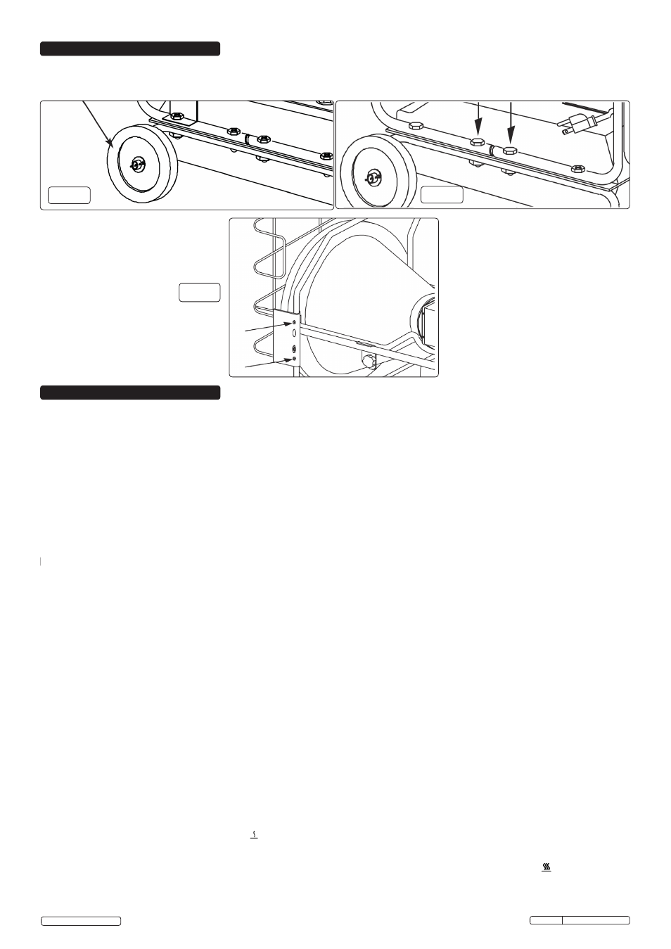
4.1. Slide axle through Wheel Frame and attach wheels, washers and cotter pins (Fig.2).
4.2. Place main structure on Wheel Frame and fasten with nuts and bolts provided (Fig.3).
4.3. Attach Safety Guard to front of heater with bolts provided (Fig.4).
Fig.2
Fig.4
Fig.3
WARNING! This heater is not suitable for use with Bio-Diesel; use of Bio-Diesel will damage the filter and seals.
Damage caused by use of Bio-Diesel will not be covered by warranty.
4. ASSEMBLY
5. OPERATION
Original Language Version
IR37.V3 Issue:4(I) - 18/02/15
© Jack Sealey Limited