Fig.1 fig.2 – Sealey CH28110VS User Manual
Page 2
3. CERAMIC ELEMENTS
DO NOT touch an element just after switching ‘off’ power supply. Allow to cool.
Ensure that the heating elements are:
• Free of fractures and cracks and are of good general condition.
• Maximum of 1400W each.
WARNING! There are no user serviceable components inside this heater, if an element requires replacing please return to an
authorised Sealey dealer.
2. INTRODUCTION & SPECIFICATION
Tripod mounted powder coated metal construction with two ceramic heating elements provide instant heat when require. Polished reflectors to maximise
heat emission. Output controlled by rocker switches fitted to the frame. Supplied with 2m cable fitted with 32Amp/110V rated plug. Foldable legs for easy
storage.
Min. Power:
1400W
Max. Power:
2800W
Input supply:
110V 32A
Heater Dimns. (W x D x H):
360 x 120 x 380mm
Maximum Height
1560mm
Weight
14kg
Original Language Version
CH28110VS Issue: 2(l) - 12/06/15
© Jack Sealey Limited
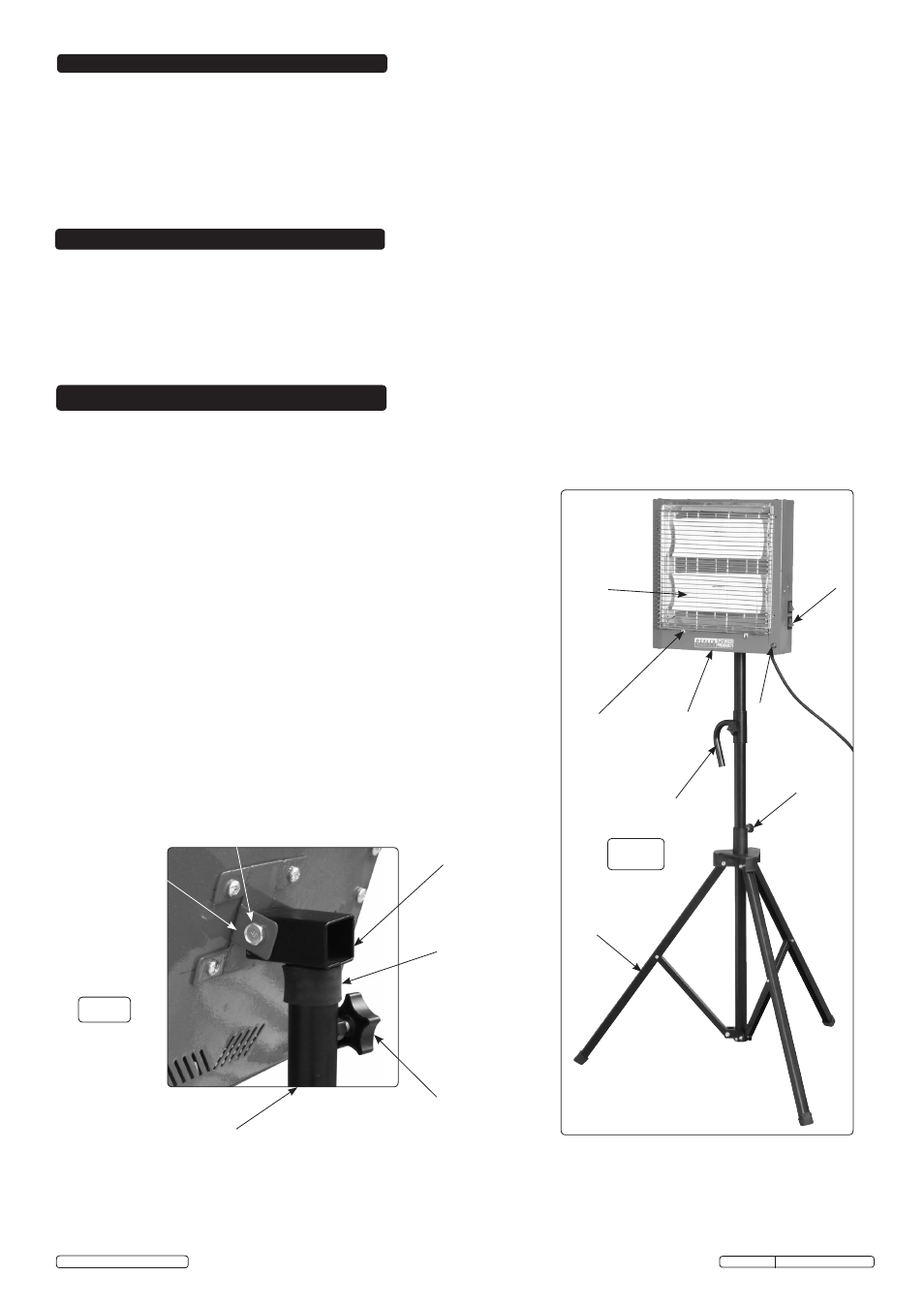
Fig.1
Fig.2
*Heater and stand Identification Fig.1
1) *Heater Element
7) Tripod
2) *Safety Guard
8) Spring loaded plunger
3) *Heater Body
9) Heater swivel mounting bracket
4) Handle and thumb screw
10) Adaptor and thumb screw
5) *Power on Neon
11) Hex screw and stiff nut
6) *Power On/Off
12) Rubber sleeve
4 c/w thumb screw
1
2
6
5
7
3
8
4. ASSEMBLY
4.1
Remove contents from packaging and check against list. In the unlikely event of
missing or damaged parts contact your Sealey dealer immediately.
4.2.1 Fit adaptor [item 10] to heater swivel bracket [item 9] with M8 hexagon head
screw and hexagon stiff nut [item 11] in (fig.2). Torque screw to obtain grip
without clamping the heater bracket totally. The heater angle can be adjusted
about this fixing between constraints.
4.2.2 The tripod will be supplied assembled. Retract plunger [item 8] in (fig.1) and pull
or push central column tube through sleeve
until the plunger "clicks" into the
next location hole. This will be the stands maximum height setting.
4.2.3
Slide the handle [item 4] down the central column and fix with the thumb screw
through the M8 hole.
4.2.4 Fit the rubber sleeve [item 12] into the top of the central column in (fig.2).
4.2.5 Slide adaptor c/w heater into central column full depth and clamp with thumb
screw.
10
9
11
12
Thumb screw
Central column
HEATER VIEWED FROM REAR