Fig.1, Fig.2 fig.3, Introduction & specification – Sealey SA5040 User Manual
Page 2: Preparation, Operation
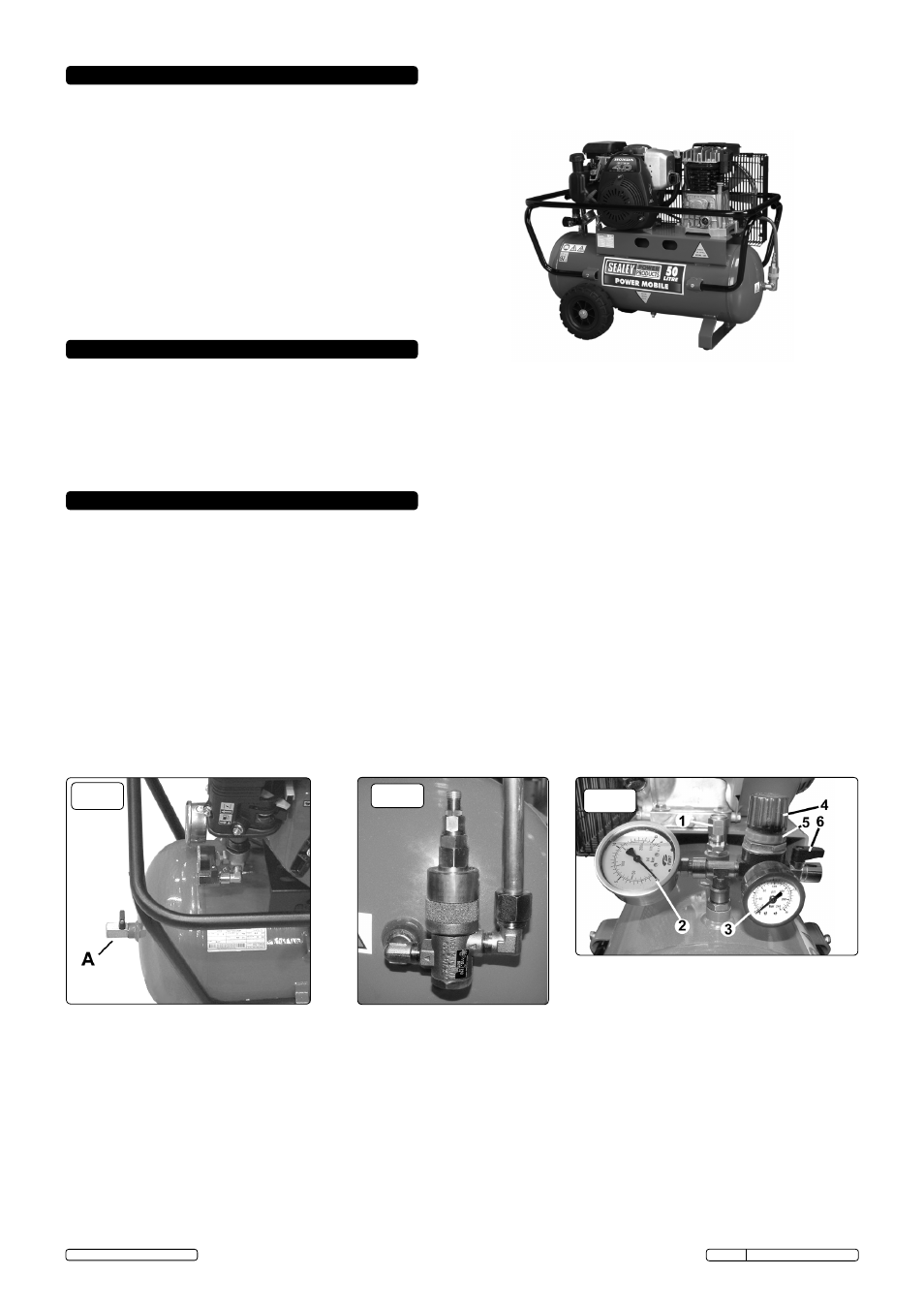
2. INTRODUCTION & SPECIFICATION
Fully mobile compressor powered by a Honda Gc 4.0hp petrol engine coupled to a heavy-duty, twin piston, cast iron pump. Fitted heavy-duty
rubber transport wheels and protected by a 360° roll cage. Features twin gauges, air outlet regulator, and a 50 litre tank.
3. PREPARATION
3.1.
Remove compressor from packaging and inspect for any missing parts or damage. If anything is found to be missing or damaged
contact your supplier.
3.2.
Save the packing material for future transportation of the compressor. It is recommended to store the packing in a safe location, at
least for the period of the guarantee. Then, if necessary, it will be easier to send the compressor to the service centre.
3.3.
If not already fitted, fit the wheels and rubber feet to the compressor with the nuts, washers etc. supplied.
3.4.
The compressor should be located in a position that allows good air circulation around the unit and where there is good ventilation.
Remember that the compressor engine produces harmful exhaust fumes.
2.1. SPECIFICATION
4. OPERATION
WARNING! Ensure that you read, understand and apply Section 1 Safety Instructions.
4.1. STARTING
IMPORTANT! Always check and, if necessary, top-up the engine oil and the pump oil before starting. Severe engine and/or pump
damage may otherwise result.
4.1.1. check that the air outlet valves - one on the tank end-plate
(fig.1.A) and one on the regulator (fig.3.6) - are closed.
4.1.2. Start the compressor engine, following the procedure detailed in the manufacturer’s handbook supplied.
4.1.3. When the engine is running smoothly, the compressor will operate automatically, building up the pressure in the tank, which is shown on
the pressure gauge (fig.3.2), to the maximum setting (factory set). When the maximum tank pressure is reached, the relief valve (fig.2)
will automatically vent the pump output. When the tank pressure falls below the minimum threshold (approx.2 bar/29psi less
than the maximum pressure), the relief valve will automatically close, and the tank pressure will increase back to it's maximum.
Note: a)
If the relief valve does not cut in and out, but is continuously closed whilst using an air appliance, the capacity of the compressor
may be too small for the equipment or tool.
b) The larger gauge (fig.3.2) indicates the pressure inside the tank, nOT the pressure supplied to the air equipment. If the pressure in
the tank exceeds the relief valve maximum, a safety valve (fig.3.1) will open.
WARNING! For this reason DO NOT tamper
with, or adjust, the relief valve or the safety valve.
fig.1
Model No: . . . . . . . . . . . . . . . . . . . . . . . . . .SA5040
Motor Type . . . . . . . . . . . . . . Honda Gc135 Petrol
Engine Output: . . . . . . . . . . . . . . . . . . . . . . . .4.0hp
Noise Level: . . . . . . . . . . . . . . . . . . . . . . . .97dB(A)
Air Displacement:. . . . . . . . . . .10.7cfm(303ltr/min)
Maximum Free Air Delivery: . . .7.8cfm(220ltr/min)
Width x Depth x Height:. . . . . 970 x 470 x 730mm
Tank Capacity: . . . . . . . . . . . . . . . . . . . . . . . . .50ltr
Maximum Pressure: . . . . . . . . . . . . . .145psi/10bar
Weight: . . . . . . . . . . . . . . . . . . . . . . . . . . . . . . 63kg
fig.2
fig.3
4.2. STOPPING.
4.2.1. To stop the compressor turn the engine ignition switch (fig.4) to Off (O). See the engine manufacturer’s handbook for the complete
engine shutdown procedure.
4.3.
CONNECTING AIR POWERED EQUIPMENT.
4.3.1. After fitting the desired coupling to the outlet valve (fig.3.6), connect the air hose and equipment.
4.3.2. Adjust the regulator valve to the required output pressure (in accordance with the air equipment instructions) by turning the regulator
knob (fig.3.4) and locking it in position with the locking ring (fig.3.5), at the required pressure (see output gauge, fig.3.3). Turn on outlet
valve (fig.3.6).
Note: To determine the correct working pressure and air flow requirements for any piece of equipment check the corresponding manual. Be
aware that the air flow figure stated on tools and accessories refers to ‘Free Air Delivery’ and not the piston displacement of the
compressor. When adjusting the regulator, always adjust
up to the required pressure.
4.3.3. To disconnect equipment, turn the regulator knob anti-clockwise to ‘zero’ (0) bar. Operate the equipment to depressurise the air line
and then disconnect from the compressor.
Original Language Version
SA5040 Issue: 2 (SP) - 23/08/13
© Jack Sealey Limited 2013